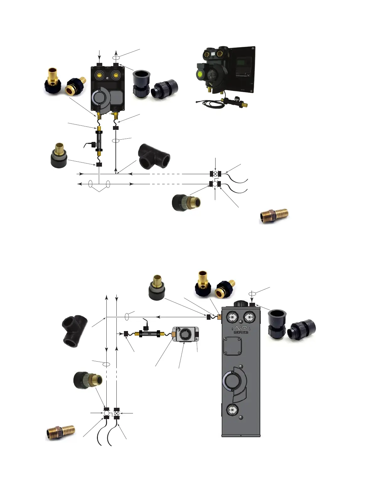
Flo-Link x 1-1/4”
PE fusion**
To/From Ground Loop
1-1/4” or 2” HDPE
NOTE: If 2”, a 1-1/4” to 2”
coupling is required
To
Unit #1
1-1/4” HDPE
1-1/4” x 1-1/4”
x 1-1/4” fusion T
1-1/4” fusion x
1” MPT adapter
1” Ball
Valve
1” MPT x 1”
hose barb***
1” rubber hose***
From
Unit #2
To
Unit #2
(same
connections
as unit #2)
1-1/4” fusion x
1” hose barb
Flo-Link x 1”
MPT w/tting
for PT Port*
From
Unit #1
6” to 8” piece of
1” rubber hose
1-1/4” HDPE
Flow Sensor
Panel mount
version available
with factory
wired controls.
1” Zone
Valve
††
Figure 4a: Two Unit Piping Diagram: Pressurized Flow Center
From
Ground
Loop
From
Unit #1
To
Unit #1
1-1/4” HDPE
1-1/4” x
1-1/4”
x 1-1/4”
fusion T
1-1/4” fusion x
1” MPT adapter
1” Ball
Valve
1” MPT x 1”
hose barb***
1” rubber hose***
From
Unit #2
To
Unit #2
(same
connections
as unit #2)
1/2 of Flo-Link x
1-1/4” PE fusion set
1-1/4” or 2” HDPE
NOTE: If 2”, a 1-1/4” to 2”
coupling is required
1/2 of Flo-Link x 1”
hose barb set with
tting for
PT Port*
1-1/4” fusion x
1” hose barb
1-1/4” HDPE**
6” to 8”
piece of
1” rubber
hose
1-1/4” fusion x
1” hose barb
Flow Sensor
1/2 of Flo-Link x 1”
hose barb set with
tting for PT Port*
To
Ground
Loop
3-Way
Valve
1/2 of Flo-Link
x 1-1/4” PE
fusion set
1” Zone
Valve
††
Figure 4b: Two Unit Piping Diagram: Non-Pressurized Flow Center
kit