Appendix F1: Pressurized Variable Speed Flow Center Submials
GEO-FLO PRODUCTS CORPORATION
905 Williams Park Drive
Bedford, IN 47421
Phone: 812-275-8513 Fax: 812-275-8523
www.geo-o.com
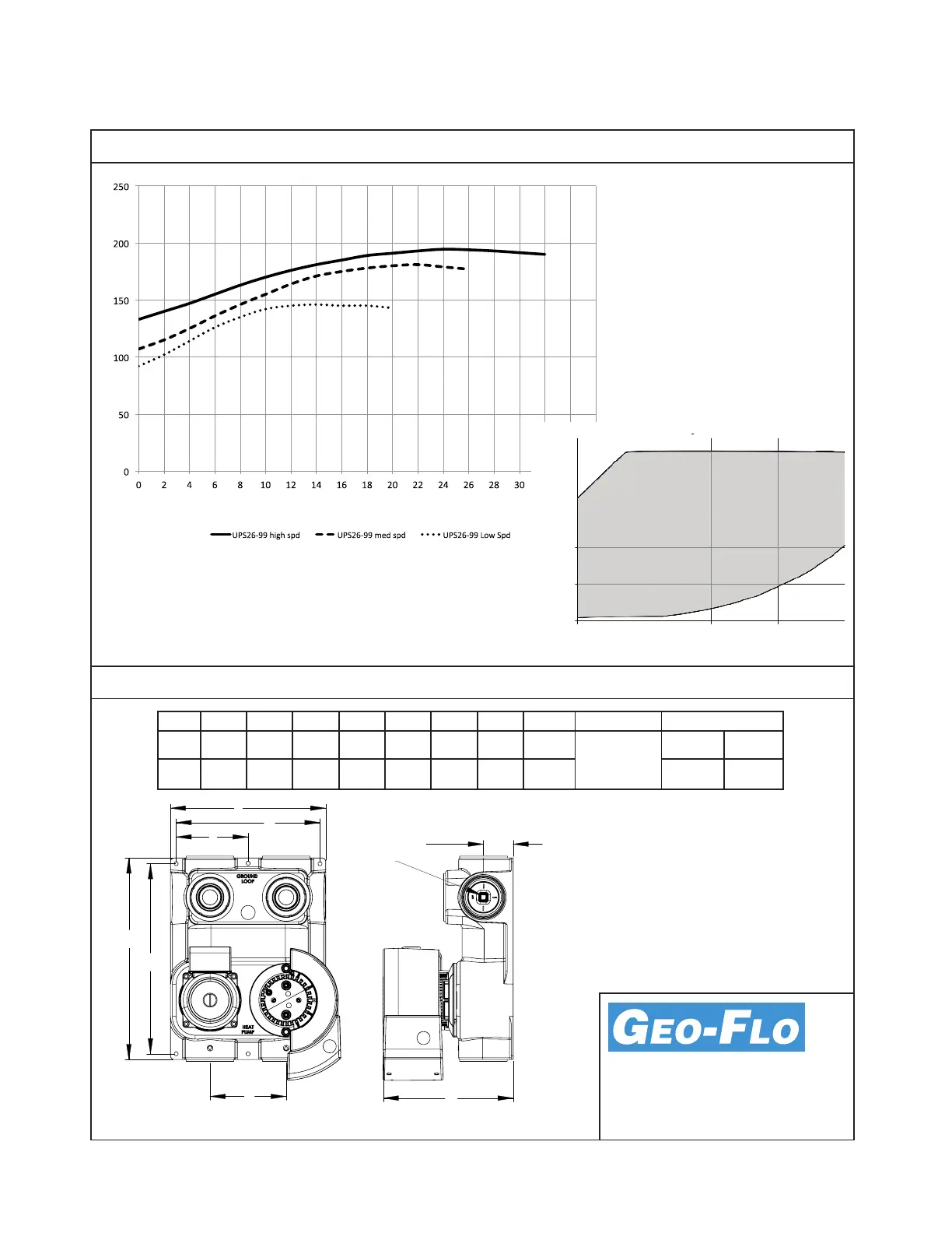
Dimensional Data
13-1/4 5
A WEIGHTIHGFEDCB
Inches
CM
LBS KG
3/8”
DRIVE
SOCKET
212-1/24-3/49-7/168-1/210-3/16
33.6 5.031.712.024.021.625.9 12.7
E
A
D
F
B
H
G
C
I
13.630.0
Pump Power Curves
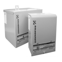
Fluid connections are Flo-Link™ double O-ring
style. Transition ttings are not included with
the ow center packaging. Typically, PE fusion
x Flo-Link is used on the ground loop connec-
tions. A Geo-Flo hose kit designed for Flo-Link
connections includes transition ttings for heat
pump connections.
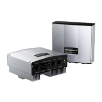
Flow center may be eld modied to a one
pump ow center by replacing the constant
speed pump with a blank plate kit.
SD 1299 rev. 24SEP2013
Flow (U.S. GPM) [l/s]
Grundfos UPS26-99 Power Curves
Power (Was)
[0.13 0.25 0.38 0.50 0.63 0.76 0.88 1.00 1.14 1.26 1.39 1.51 1.64 1.77 1.89 2.02 2.15 2.27]
0 10 20 30 40
Flow (U.S. GPM) [l/s]
Grundfos Magna GEO 32-140 Power
0
50
100
150
200
250
Power (Was)
[0.63 1.26 1.89 2.52]
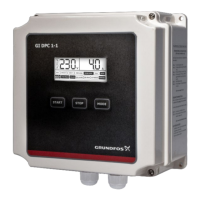
NOTES: The Magna GEO (variable speed)
pump adjusts speed (when used with con-
troller) to maintain ow rate or tempera-
ture dierence. The controller energizes
the constant speed pump (UPS26-99) when
the Magna GEO cannot meet setpoint, and
adjusts the Magna GEO pump accordingly.
Total ow center Was equals constant
speed pump Was plus Magna GEO Was
at design condions. For Was based upon
a specic ow rate and pressure drop, go to
www.geo-o.com, and use the pump sizing
calculator.