Rev. 05JUL2016
B.
C.
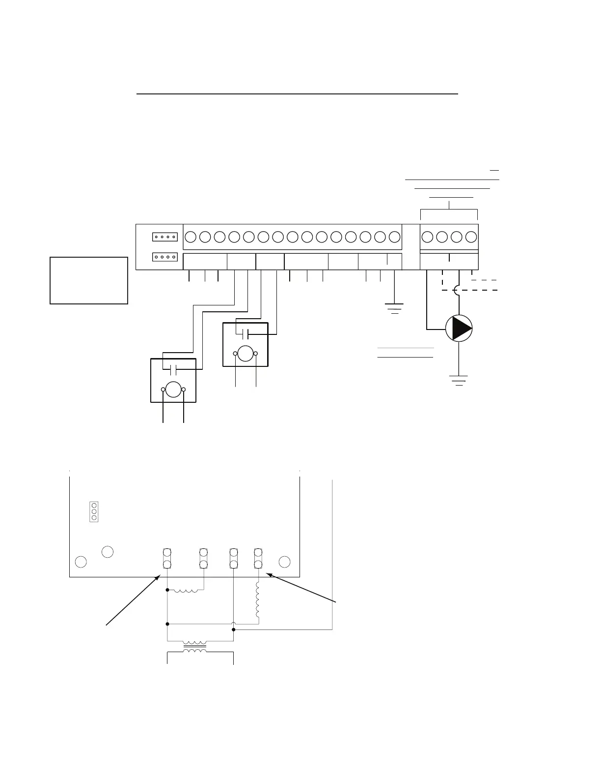
24 VAC Input to Power
Controller
Note 3
24VAC Input Signal
(Note 2)
24VAC Input Signal
(Note 1)
Magna GEO Pump
Grundfos Direct
Sensor Inputs
1-10 VDC Input
Earth Ground
Thermistor
Inputs
Brown
Black
Blue
Entering Water Therm (from loop)
Leaving Water Therm (to loop)
Thermistors Common
4-pin connector from
Grundfos Flow Sensor
on either Entering OR
Leaving Water side
LWT
EWT
OUT
IN
REF
PWM
HP IN1 HP IN2
LWT
EWT
C
THERMS
+
-
1-10 DCIN
24VAC IN
GND
AUXILIARY
L1 L2
N1 N2
OUT OUT
ININ
BRN
BLK
BLU
(Note A)
208-230 VAC Input/Output
Power to UPS26-99 (2nd pump)
for two pump flow centers. Do
not connect Magna GEO single
pump flow center to this
terminal block.
Line Voltage Wiring
(115V or 230V)
UPS26-99 (2nd pump)
Do not connect to
Magna GEO pump.
115V
or 230V
pump
(Note B)
(Note C)
ACC
LP1 HP2HP1YLP2 FLOW
SWITCH
LPS
HPS
FLOW
T-STAT
NO
STATUS
TEST
YES
C R CCFAULT
Fault
Contactor
Coil
CC
Compressor
Contactor
Coil
24 VAC
230 VAC
Use for ACC
connection*
Find an easy
to access
Common (C)
connection*
*May require a “piggyback” spade connector.
Typical WSHP Lockout Board Without an Accessory Terminal
Important Wiring Notes for Variable Speed Flow Centers:
Heat Pumps Without an Accessory Terminal
Many geothermal heat pumps have an accessory terminal (sometimes labeled “A” or “ACC”). One of the
purposes for the accessory terminal is for control of a solenoid valve for open loop systems. However,
it also aects the operation of the Grundfos UPC-GEO variable speed pump controller. This document
will address wiring for systems without an accessory terminal.
The accessory terminal is typically connected to the output from the lockout board to the compressor
contactor coil (labeled “CC” in the example below). The compressor contactor is only energized after
the anti-short cycle delay, and if there are no lockouts. If the water solenoid is connected between “C”
(common) and the heating/cooling thermostat terminal (”Y” or “Y1”), the solenoid will be energized
any time there is a thermostat call. Most of the time, this approach works ne. However, if the heat
pump is locked out, the water will continue to run even when the compressor is locked out, potentially
causing substantial use of water and electricity for the pump. Therefore, using the “CC” connection to
engage an accessory ensures that the solenoid valve will not open if the unit is locked out.
NOTE: This only applies to solenoid valves without an end switch. Solenoid valves with an end switch
must be wired to the thermostat heating/cooling terminals.
A similar issue could occur with the variable speed pump controller. If the heat pump is locked out, and
the controller is in temperature dierence (∆T) mode, the thermostat will continue to call, but there will
be no ∆T because the compressor is o. Once the heat pump is reset, the controller may not be able to
react qucikly enough, potentially causing insucient water ow. When an accessory terminal is used,
the control will only be enabled when the compressor contactor is energized.
If the heat pump being installed/serviced does not have an accessory terminal, the example diagram
below provides suggestions for simulating an accessory terminal.
NOTES:
D.
E.
IMPORTANT:
Controller must
be grounded.