6
Original installation and operating instructions.
CONTENTS
Page
1. Symbols used in this document 6
2. Scope of these instructions 6
3. Product description 6
4. Nameplate 7
5. Type key 7
6. Operating conditions 8
7. Installation 8
7.1 Mechanical installation 8
7.2 Electrical installation 9
8. Control panel 9
9. Start-up 9
10. Operating modes 9
10.1 Manual operation 9
10.2 Automatic operation 9
10.3 Dry-running protection 9
10.4 Emergency operation 10
11. Functions 10
12. Settings 10
12.1 Setting the pressure switches 10
12.2 Setting the diaphragm tank pre-charge pressure 11
13. Maintenance 11
13.1 Pump 11
13.2 Settings 11
13.3 Frost protection 11
14. Fault finding chart 12
15. Related documentation 12
16. Disposal 12
1. Symbols used in this document
2. Scope of these instructions
These installation and operating instructions apply to Grundfos
Hydro Multi-S booster sets.
Hydro Multi-S is a range of factory-assembled booster sets, ready
for installation and operation.
3. Product description
The Grundfos Hydro Multi-S booster set is designed for pressure
boosting of clean water.
Examples:
• blocks of flats
• hotels
•schools.
Hydro Multi-S consists of two or three identical Grundfos CH or
CR pumps connected in parallel and mounted on a common base
frame, suction and discharge manifolds, isolating valves, non-
return valves, pressure gauge, pressure switches and a control
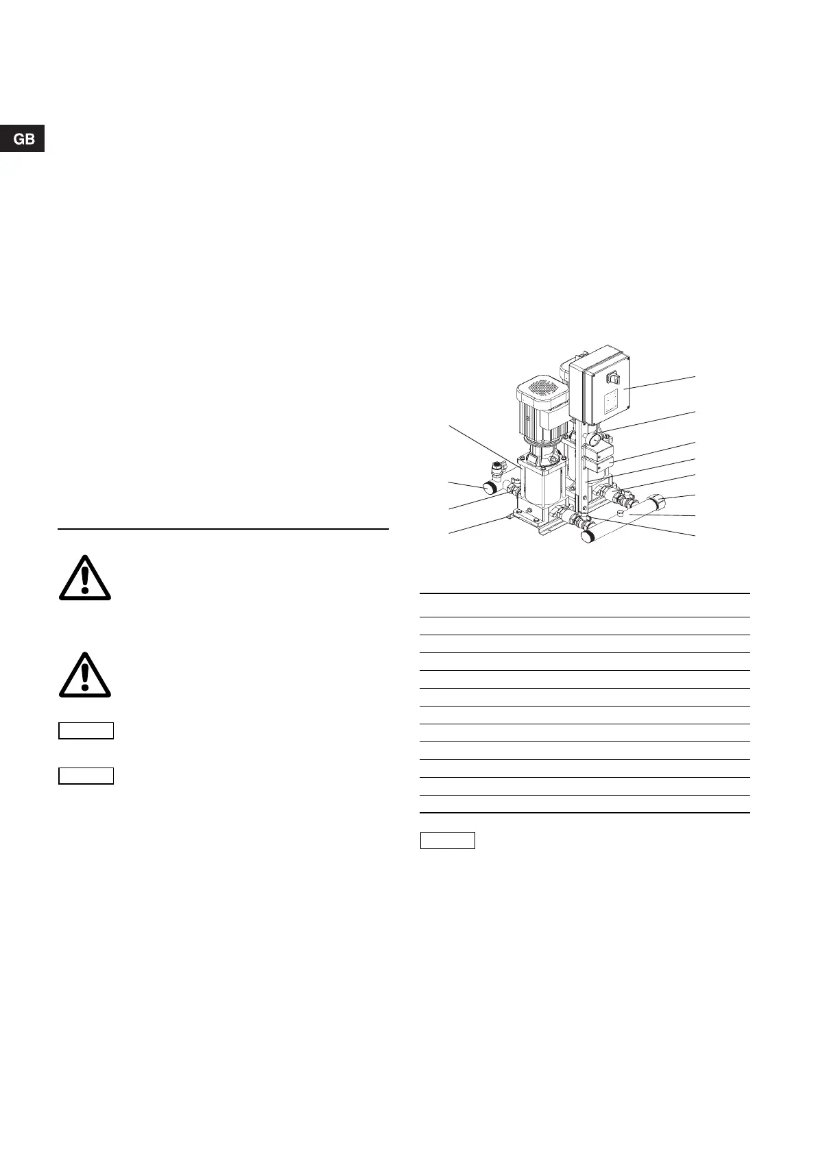
cabinet. See fig. 1.
Fig. 1 Hydro Multi-S booster set
Warning
Prior to installation, read these installation and
operating instructions. Installation and operation
must comply with local regulations and accepted
codes of good practice.
Warning
If these safety instructions are not observed,
it may result in personal injury!
If these safety instructions are not observed,
it may result in malfunction or damage to the
equipment!
Notes or instructions that make the job easier
and ensure safe operation.
TM03 9724 4307
Pos. Components
1 Pumps (Grundfos CH or CR)
2 Discharge manifold
3 Isolating valves
4 Base frame
5 Control cabinet
6 Pressure gauge
7 Pressure switches
8 Stand
9 Non-return valves
10 Screw caps
11 Suction manifold
A diaphragm tank must always be installed on
the discharge side of the booster set.