English (GB)
17
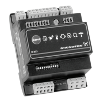
6.3 User interface
Fig. 20 IO 113 module
6.4 Indicator lights and their function
On the front, IO 113 has seven indicator lights for
sensor status. Figure 21 shows the location of lights
on IO 113, and the table explains their meanings.
Fig. 21 Indicator lights on IO 113
TM05 1881 3811
Pos. Description
1 Terminals for alarm relay
2
Terminals for analog and digital inputs and
outputs
3 Terminals for supply voltage
4
Potentiometer for setting the warning limit of
stator insulation resistance
5
Terminals for RS-485 for GENIbus or
Modbus
6 Indicator light for measurement of moisture
7 Indicator light for stator insulation resistance
8 Indicator light for leakage (WIO/WIA)
9 Indicator light for vibration in pump
10
Terminals for measurement of stator
insulation resistance
11 Terminals for connection of pump sensors
12 DIP switch for configuration
13 Indicator light for motor temperature
14 Button for resetting alarms
15 Indicator light for motor running
16 Indicator light for service
17 Terminals for digital outputs
PET1 T2
G1 A1 G2 A2 K1 K2 R1 R2
D1 D2 D3 D4 D5 D6 D7 D8
P1 P2 P3 P4 P5
AYB
I1 I2 I3
ON DIP
12345678910
11 1 2
12 3
4
5
6
7
8
9
1011
TM05 1968 4111