English (GB)
24
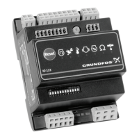
9. Overview of alarms and warnings
IO 113 has two categories of fault:
1. Alarm. The pump stops. The fault is related to a
primary functionality (e.g. motor temperature too
high). The relay opens and breaks the connection
between T1 and T2 in case of alarm or if IO 113
is not connected to the power supply. An alarm is
shown by the indicator lights on the front panel of
IO 113 and via the four digital outputs. See fig. 20
(17).
2. Warning. The pump does not stop. The fault is
related to a secondary functionality (e.g. too
much water in the oil). A warning is shown by the
indicator lights on the front panel of IO 113. The
warning status can be read via the digital outputs
D7 and D8. See fig. 20 (17).
9.1 Alarm resetting
Alarms can be reset by means of terminals R1 and
R2.
Manual resetting
Alarms can be reset by short-circuiting R1 and R2.
The reset button also short-circuits R1 and R2.
Never press the reset button for more than 2
seconds to reset alarms. See section 10. Calibration.
Automatic resetting
If you make a permanent short circuit between R1
and R2, alarms will automatically be reset when the
cause of the alarm has disappeared.
Fault
Standard ATEX/IECEx protection activated
Warning Alarm Warning Alarm
Stator winding temperature too high ● ● ● ●
Moisture in top cover ● ●
Moisture in stator housing ● ●
Moisture in bottom of motor ● ●
Water in air ● ●
Missing signal from water-in-air sensor ● ●
Water in the oil exceeds limit ● ●
Missing signal from water-in-oil sensor ● ●
Insulation resistance too low ● ● ● ●
Configuration conflict ● ● ● ●
Main bearing temperature too high* ● ● ●
Support bearing temperature too high* ● ● ●
Missing signal from bearing sensor* ● ●
Communication fault* ● ●
Time for service ● ●
Internal fault ● ●
Vibrations exceed limit ● ● ● ●
* Pump with SM 113