English (GB)
8
3.5.2 Electrical connection
All terminals are rated for maximum 8 A.
Terminals 1, 2, 3, 5, 10 and 11 are for wire size 0.08
- 3.3 mm
2
(AWG 28-12); terminal 17 is for wire size
0.08 - 1.3 mm
2
(AWG 28-16). For voltage rating of
the individual terminals, see section 3.5 Electrical
connection.
For terminals 5 and 17, one 3-hole socket and one
8-hole socket are provided as accessories in the
package.
Terminals T1 and T2 are normally connected to 220-
240 VAC. See fig. 20, pos. 1.
Terminal I3 may be connected to up to 600 VAC. See
fig. 20, pos. 10 and the diagrams at the end of these
instructions.
4. Configuring the product
4.1 Potentiometer
Set the warning limit for stator insulation resistance
by means of a potentiometer. See fig. 20 (4). The
warning limit can be set between 1 and 10 MΩ. The
alarm limit is 1 MΩ.
Fig. 4 Potentiometer
4.2 DIP switch configuration
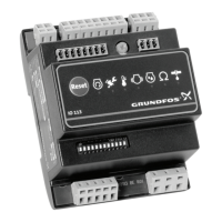
IO 113 must be configured for the connected pump
by means of the DIP switches. See fig. 20 (12).
Fig. 5 Shows that all DIP switches are in OFF
position
A configuration alarm will be given in the following
cases:
• The configuration does not correspond to the
pump connected.
• The configuration fault is of safety-related
importance (see section 6.7 Approval).
A configuration warning will be given if the
configuration fault is of function-related importance
(see section 6.7 Approval).
The insulation between the cabinet in
which the module is fitted and the sensor
input terminals must have a dielectric
strength of 2210 VAC, or the cabinet must
be connected to earth.
External controllers connected to the IO
113 module via the RS-485 connection
must meet the requirements of IEC 60950-
1 or 61010-1 (USA: UL 60950-1).
If SM 113 is used in the installation,
connect a PTC sensor to IO 113.
TM03 3415 0306
TM05 1978 4111

 Loading...