English (GB)
6
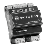
3.5 Electrical connection
3.5.1 Wiring diagrams
The wiring diagrams below show the regular applications of WIO/WIA sensors, moisture switch, thermal
switches, Pt100/Pt1000/PTC sensors, as well as sensor monitoring board SM 113 with speed sensor, vibration
sensor and components.
For information about setting the DIP switches, see section 4.2 DIP switch configuration.
TM05 2493 0112
TM05 2794 0612
PA - Thermal switches, Pt1000
sensor, moisture switch, WIO/
WIA sensor
PB - With SM 113. Thermal switch, moisture switch, WIO/WIA
sensor, Pt100/Pt1000 sensor
P1 P2 P5P3 P4
IO 113
WIO / WIA
Pt1000
ON
12
Moisture switch
Thermal
switches
1234567891011121314
SM 113
P1 P2 P5P3 P4
Pt100 / Pt1000
WIO / WIA
IO 113
Moisture switch
Thermal
switches
TM05 2494 0112
TM05 2795 0612
PA - Thermal switches, PTC
sensor, moisture switch, WIO/
WIA sensor
PB - With SM 113. Thermal switches, moisture switch, WIO/WIA
sensor, Pt100/Pt1000 sensors
P1 P2 P5P3 P4
IO 113
WIO / WIA
PTC
ON
12
Moisture switch
Thermal
switches
1234567891011121314
SM 113
P1 P2 P5P3 P4
Pt100 / Pt1000
WIO / WIA
IO 113
Moisture switch
Thermal
switches
TM05 2789 0612
TM05 2796 0612
PA - Thermal switches, moisture
switch, WIO/WIA sensor
PB - With SM 113. Thermal switches, moisture switch, WIO/WIA
sensor, Pt100/Pt1000 sensors, vibration sensor
P1 P2 P5P3 P4
IO 113
WIO / WIA
ON
12
Moisture switch
Thermal
switches
1234567891011121314
SM 113
P1 P2 P5P3 P4
Pt100 / Pt1000
WIO / WIA
IO 113
Moisture switch
Thermal switches
Vibration
sensor