6
CONTENTS
Page
1. Symbols used in this document 6
2. General information 6
3. Applications 6
4. Technical data 6
5. Installation 6
6. Electrical connection 7
6.1 Checking the direction of rotation
(three-phase motors) 7
7. Start-up 7
7.1 Frost protection 7
7.2 Ejector valve setting 7
8. Cleaning the pump 8
8.1 Dismantling 8
8.2 Assembly 8
9. Fault finding chart 9
10. Disposal 9
1. Symbols used in this document
2. General information
These instructions apply to JP 5 and JP 6 pumps in
material variants A and B.
The JP pumps are available with or without ejector
valve.
3. Applications
The Grundfos jet pumps, type JP, are horizontal,
self-priming centrifugal pumps designed for pumping
water and other thin, non-aggressive liquids, not
containing solid particles or fibres.
If the pump has been used for dirty liquids, e.g. pool
water, it must be flushed through with clean water
immediately after use.
4. Technical data
Ambient temperature
Maximum +40 °C.
Liquid temperature
See pump nameplate.
System pressure
Maximum 6 bar.
Inlet pressure
At inlet pressures above 1.5 bar, the discharge
pressure must be at least 2.5 bar.
Supply voltage
According to the pump nameplate – 10 %/+ 6 %.
Enclosure class
IP44.
Relative air humidity
Maximum 95 %.
Dimensions and weights
Dimensions: See page 145.
Weights: See label on the packing.
Sound pressure level
The sound pressure level of the pump is lower than
72 dB(A).
5. Installation
The pump must be installed horizontally.
When the suction pipe is longer than 10 metres or
the suction lift is greater than 4 metres, the diameter
of the suction pipe must be larger than that of the
pump suction port (S). If there is a suction lift, it is
recommended to fit a non-return valve to the suction
pipe.
If a hose is used as suction line, it must be of a non-
collapsible type.
To prevent solids from entering the pump, a filter can
be fitted to the suction pipe.
When installing the pipes, it must be ensured that the
pump is not stressed by the pipework.
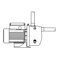
Connect the discharge pipe to the pump discharge
port (T). See fig. 1. H = maximum 8 metres.
Fig. 1 Pipework connection
Warning
Prior to installation, read these
installation and operating instructions.
Installation and operation must comply
with local regulations and accepted
codes of good practice.
Warning
If these safety instructions are not
observed, it may result in personal
injury!
Caution
If these safety instructions are not
observed, it may result in malfunction
or damage to the equipment!
Note
Notes or instructions that make the job
easier and ensure safe operation.
Warning
The pump must not be used for the
transfer of inflammable liquids such as
diesel oil, petrol or similar liquids.
TM00 5494 4995
S
T
H max.
8 m
H

 Loading...