8
8. Cleaning the pump
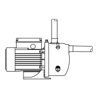
The position numbers mentioned in the following
sections refer to fig. 5.
8.1 Dismantling
1. Pumps fitted with ejector valve only: Turn the
ejector valve to pos. A. See fig. 4.
2. Drain the pump by removing the plug (pos. 25) or
the ejector valve (pos. 25a).
Note: The escaping water may be hot.
3. Remove the screw (pos. 93) and the clamp
(pos. 92) holding the pump sleeve (pos. 16).
4. Push the pump sleeve (pos. 16) free of the motor
stool with a screwdriver, and take it off.
5. Pull the ejector (pos. 14) out of the pump sleeve.
6. Clean the ejector and the pump sleeve using a
brush or a water jet.
7. Check that the impeller (pos. 49) is not dirty.
If that is the case, remove the impeller.
To prevent the motor shaft from rotating, hold the
fan blades. Remove the nut from the motor shaft.
8. Clean the impeller using a brush or a water jet.
Carefully clean the shaft seal space under the
impeller.
8.2 Assembly
1. Screw the impeller (pos. 49) onto the motor shaft.
The external hexagon of the shaft must engage
with the internal hexagon of the impeller. Fit the
nut (pos. 67) to the motor shaft and tighten.
2. Moisten the O-ring (pos. 13) with soapy water,
and fit it into the recess of the suction port of the
ejector (pos. 14).
3. Fit the ejector into the pump sleeve (pos. 16).
Check that the O-ring (pos. 13) is positioned
correctly on the collar of the suction port of the
sleeve.
4. Moisten the O-ring (pos. 31) with soapy water,
and place it on the ejector.
5. Moisten the seal ring (pos. 91) with soapy water,
fit it into the recess of the ejector, and turn it
against the stop.
6. Fit the pump sleeve with the ejector to the motor
stool. Check that the O-ring (pos. 31) is
positioned correctly.
7. Place the clamp (pos. 92) on the pump sleeve,
and refit the screw and nut and tighten securely.
8. Refit the plug (pos. 25) or the ejector valve
(pos. 25a). Check that the ejector valve is in
pos. A. See fig. 4. Tighten the plug or ejector
valve using fingers only.
In orders for spare parts, please mention the position
number in fig. 5 and the pump data marked on the
pump nameplate.
Fig. 5 Exploded view of jet pump
Warning
Before starting work on the pump,
make sure that the power supply has
been switched off. It must be ensured
that the power supply cannot be
accidentally switched on.
TM00 5498 2308
Note
The pump illustrated in fig. 5 may differ
from the actual pump version.

 Loading...