7
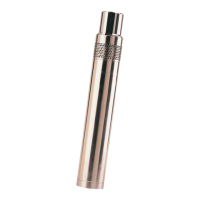
The level of the liquid in the motor should be checked before the pump is installed.
1. Place the pump and motor in a vertical position with the discharge port pointing
downwards(i.e.thebottomofthemotorisuppermost),andremovethelling
screw.Seeg.4.
2. Ifthewaterstandsuptotheedgeofthethreadedhole,nollingisrequired.
Ifnot,lldemineralisedwaterintothemotor.
Toenableallairtoescape,insertyourngerinthepumpdischargeportand
lift the shaft a few times.
Recheck the liquid level.
3. Replaceandtightenthellingscrew.
The pump is now ready for installation.
Pump discharge port: Rp 3/4.
A pipe or a hose can be connected to the pump.
Wheneverahoseistted,acompressioncouplingmustbeused.
Seeg.5.
Tightentheunionnutusingngersonlyandthengiveit11/4turnswithatool.
If PTFE pipes or hoses or unarmoured hoses are used, a stainless-steel straining
wire is required for lowering and lifting the pump.
Securethestrainingwiretothepumpwithawireholder.Seeg.6.
Lower the pump into the borehole, taking care not to damage the motor cable.
Do not lower or lift the pump by the motor cable.
During operation, the pump and motor must be completely submerged to
ensure the necessary lubrication of the shaft seal and cooling of the motor.
If the pump pumps more water that the borehole can yield, there is a risk that the water level falls below the
level of the pump inlet and that air is therefore sucked into the pump.
cooling of the motor.
If a non-return valve is installed in the discharge pipe, it must be installed above the
pump. This is necessary to ensure that the air in the pump is compressed so much that the pump contains
water when it is being submerged.
Fig.4 Removalofllingscrew
Fig. 5 Use of compression coupling
Fig.6 Fittingthestrainingwire
 Loading...