English (GB)
8
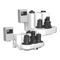
5.1.1 Collecting tank
The gas-, odour- and pressure-tight collecting tank is made of
wastewater resistant polyethylene (PE) and has all necessary
ports for the connection of inlet pipes, discharge pipe, venting
pipe and a manually operated diaphragm pump, which is
available as an accessory.
The MD collecting tank has a turnable, eccentric disk in the
back allowing adjustment of the inlet to any height between 180
and 315 mm above the floor. The most common heights are
marked beside the inlet. See section 7.3 Procedure for
installation of lifting station.
Furthermore, the MD collecting tank offers four horizontal inlets in
the sides (2 x DN 100 and 2 x DN 50) and three vertical inlets at
the top of the tank (2 x DN 150 and 1 x DN 50). The centres of the
horizontal inlets are 120 mm (DN 50) and 250 mm (DN 150)
above the floor.
The side and back inlets 180 and 250 mm above the floor are for
direct connection to wall-hung or floor-standing toilet according to
EN 33 and EN 37. Further sanitary appliances can be connected
to the other ports.
The MLD collecting tank offers one vertical inlet, DN 50, at the
top of the tank and one vertical inlet, DN 150, in the stepped part
of the tank.
The tank volume and effective volume (volume between start and
stop) for Multilift MD and MLD lifting stations appear from the
following table:
Setting to the relevant start inlet level must be made during the
start-up phase via the setup menu. See section 6.2 Setup menu.
The first step after power supply connection is a start-up phase
with level setting.
To minimise sedimentation, the tank bottom is chamfered to lead
the wastewater to the pump.
5.1.2 Pumps
The pump impellers are designed as free-flow vortex impellers,
ensuring almost unchanged performance throughout the entire
life of the pump. See the pump curves in section
12.5 Performance curves. The stator housing of the motor is
made of cast iron. The pump has a mechanical shaft seal.
See more technical data in section 12. Technical data.
Single-phase motors are protected by a thermal switch in the
windings and run via a capacitor inside the controller cabinet.
Three-phase motors are protected by a thermal switch in the
windings and an additional thermal circuit breaker in the cabinet
of Multilift MD/MLD22, 24, 32 and 38 to cut out the motor in case
of overload.
If the phase sequence for three-phase pumps is wrong, the
controller will indicate fault and prevent the pump(s) from starting.
For correction of phase sequence, see fig. 14. For direction of
rotation, see section 10.2 Motor.
5.1.3 Shaft seal
The pumps have three shaft seals, the oil chambers in between are
filled for life and therefore require no maintenance.
For replacement in case of service, please see service
instructions.
5.1.4 Motor cable
The motor cable is fitted to the motor via a cable entry.
The enclosure class is IP68. The length of the cable is either 4 m
or 10 m.
Nameplate, motor
Fig. 4 Nameplate, motor
5.1.5 Non return valve
The DN 80 non-return valve includes a drain screw to lift up the
internal flap in order to drain the discharge pipe in case of
maintenance or service. The valve is designed and tested
according to EN12050-4. See fig. 5.
Fig. 5 Butterfly (double) non-return valve, DN 80
MD
Inlet level [mm] 180 250 315
Total tank volume [l] 130
Effective tank volume [l] 49 69 86
MLD
Inlet level [mm] 560
Total tank volume [l] 270
Effective tank volume [l] 190
If the motor is overloaded, it will stop
automatically.
When it has cooled to normal temperature, it will
restart automatically.
TM03 3618 0506
Pos. Description
19 Product number and model
20 Number of phases
21 Frequency
22 Input power
23 Shaft power
24 Power factor
25 Enclosure class
26 Production country
27 CE mark
28 Production week and year
29 Operating mode
30 Rated speed
31 Weight
32 Insulation class
33 Rated voltage
34 Rated current
Loosen the lock nut a little before turning the
drain screw.
TM051530 2911
Made in Germany
kW
Hz
~
96075378 - A
kW
96075389
P. c.
min
-1
kg
n
Weight
0149 001
S3-40%-1min
1405
24
F
Insul.class
Prod.- No.
U
P
2
V
A
I
1/1
Motor
5.3
400
3
50
2.8
IP68
2.2
P
1
0.77
22
23
21
20
19
24
25
26
27
32
31
30
29
28
33
34
COS
$
 Loading...


