L1
L2
L3
T1
T2
T3
U1
V1
W1
U2
V2
W2
1
3
5
4
6
2
7
8
9
P1
P2
P5
U1
V1
W1
U2
V2
W2
1
3
5
4
6
2
7
8
9
P1
P2
P5
L1
L2
L3
L1
L2
L3
U1
V1
W1
U2
V2
W2
1
3
5
4
6
2
7
8
9
M
WIO
M
WIO
A B
C
Y&G
N/A
M
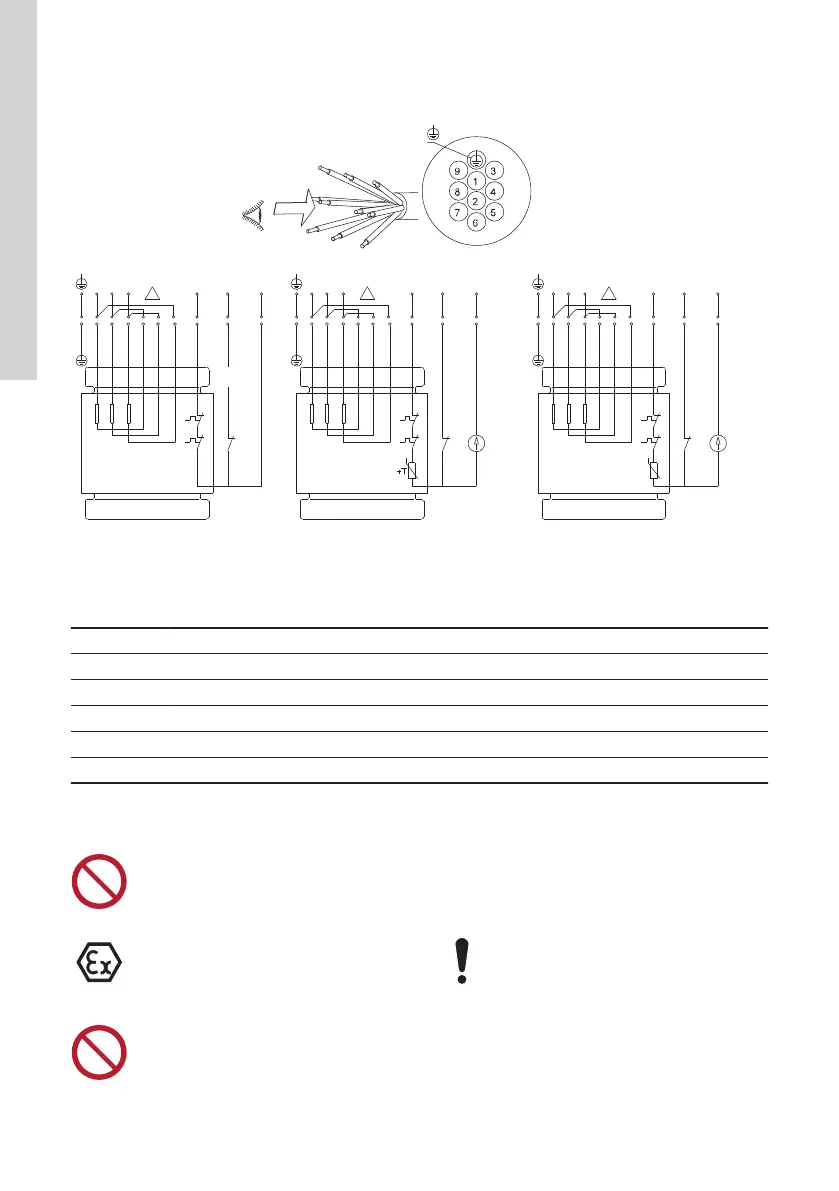
TM046887
Wiring diagram, 10-core cable, delta-connected (D)
Pos. Description
Y&G Yellow and green
N/A Sensor version with thermal switch, PTC thermistor*, moisture switch and WIO sensor
A Standard version with thermal switches
B Sensor version with thermal switch, Pt1000, moisture switch and WIO sensor
C Sensor version with thermal switch, PTC thermistor*, moisture switch and WIO sensor
*Pumps with 4 kW and larger motors sold in Australia or New Zealand are fitted with a PTC thermistor.
Starting up the product
The pump must not run
dry.
Dry running can cause
ignition hazard.
Do not open the clamp
while the pump is oper-
ating.
The pumps are fitted
with impellers of S-tube
®
design. S-tube
®
impel-
lers are wet balanced,
which reduces the vibra-
tion during operation. If
the pumps are started
with the pump housing
containing air, the
24
English (GB)
 Loading...