English (GB)
8
3.4 Tools
• Thread tape
•Glue
Not delivered with the product:
• Drilling machine
• Drilling bits: Ø6, Ø16, Ø25
• Cup saw: Ø40, Ø100
• Deburring tool for polyethylene
3.5 Installation overview
Depending on your product type, you must go
through different steps in order to install and setup
your system. The steps below are necessary steps in
order to start your system. You may need to go
through extra steps if you have additional
accessories.
Unolift/Duolift with pumps with float switches
1. Fix tank to the floor
2. Drill holes for inlet pipes
3. Connect inlets to tank
4. Fit venting port and cable glands
5. Adjust length of float switch cable to set start
levels
6. Install pumps inside tank
7. Fit inner connecting pipe
8. Fit venting pipe
9. Fit discharge pipes
Unolift/Duolift with controller and level sensor
tube
1. Fix tank to the floor
2. Drill holes for inlet pipes
3. Connect inlets to tank
4. Fit venting port and cable glands
5. Install pumps inside tank
6. Install sensor tube inside tank
7. Fit inner connecting pipes
8. Fit venting pipe
9. Fit discharge pipes
3.6 Positioning the product
Position the tank so that all components are easily
accessible during operation and maintenance.
3.7 Installing the tank
Fix the tank to the floor to prevent uplift and twist.
Use the mounting brackets to fix the tank with
screws.
3.8 Drilling holes in the tank
Depending on the size, the the tank has three to four
pre-moulded holes ∅ 100 for the inlet pipes. The
tank also has a pre-mouled hole ∅ 40 for the
diaphragm pump. See section 5.1 Product overview.
These holes must be cut opened in order to be used.
Holes for discharge pipes, venting pipe and minimum
required cable glands are already opened.
The minimum required cable glands depend on the
model:
• Unolift, APB, CC, KP: one hole opened for pump
cable
• Unolift SEG: two holes opened for pump cable
and sensor hose
• All Duolifts: three holes opened for pump cables
(2) and sensor hose (1)
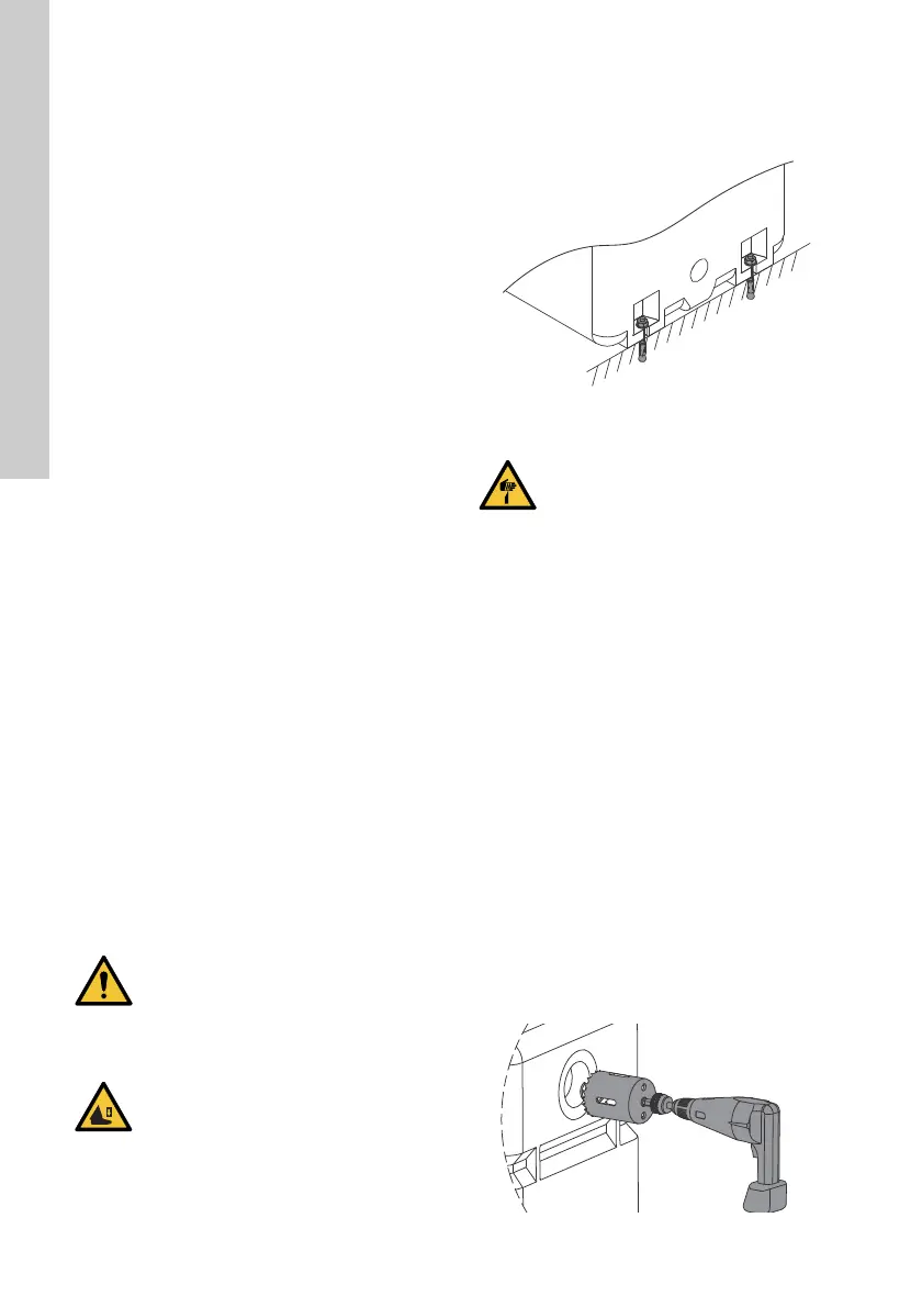
3.8.1 Drilling holes for pipes
1. Determine which inlets you want to use.
See “Choice of tank inlets” on page 6.
2. Drill holes with a cup saw.
The diameter of the cup saw must be the same
as the diameter of the pipe.
Inlet: Ø100
Outlet, pipe for diaphragm pump: Ø40
3. Deburr the holes.
Fig. 3 Drilling holes for pipes
CAUTION
Back injury
• Minor or moderate personal injury
• Get assistance from another person or
use lifting equipment to carry the
product.
CAUTION
Crushing of feet
• Minor or moderate personal injury
• Wear safety shoes when moving the
product.
TM065780 0116
CAUTION
Sharp element
• Minor or moderate personal injury
• Wear protective gloves.
TM065851 0216
 Loading...