10. Service
PNEG-1717 CE Approved GSI/FFI Portable Dryer Manual 59
Installing the Fan Blade Assembly (Continued)
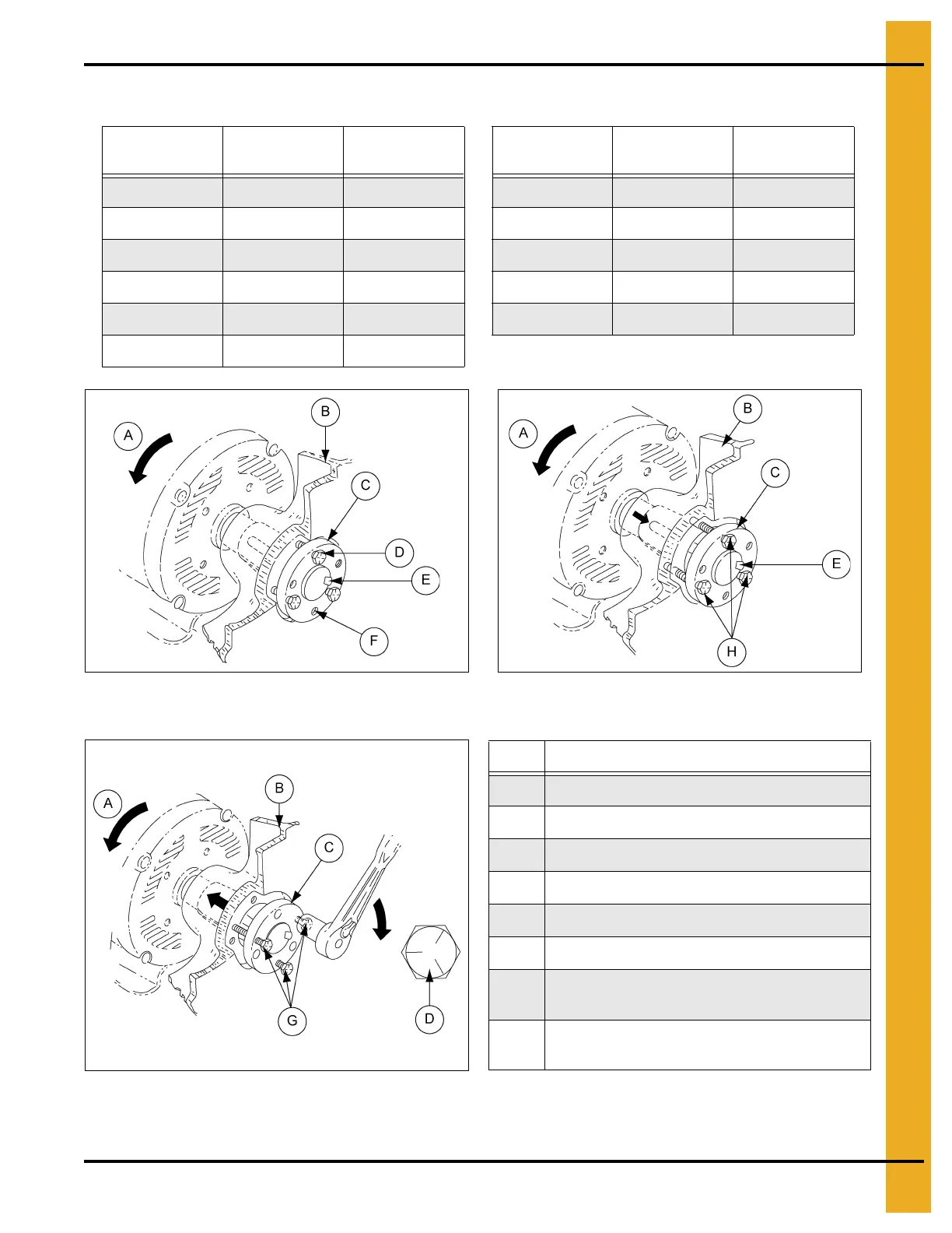
Figure 10C Cutaway Drawing of Typical Propeller
Installation
Figure 10D Cap Screw Arrangement for Disassembly
Figure 10E Cap Screw Arrangement for Resassembly
Bushing Bolt Thread
Bolt Torque
(Nm)
Bushing Bolt Thread
Bolt Torque
(Nm)
JA 864 mm 6.75 P-1 465 mm 17.55
G 514 mm 8.10 SK 465 mm 20.25
H 514 mm 8.10 SF 416 mm 31.05
SH 514 mm 10.80 Q-1 416 mm 39.15
SD 514 mm 12.15 R-1 416 mm 39.15
SDS 514 mm 12.15
Ref # Description
A Rotation
B Propeller
C Taper-Lock Bushing
D Cap Screw (Grade 5)
E Key
F Threaded Holes in Bushing
G
Cap screws installed into threaded holes to force
propeller off bushing.
H
Cap screws installed through clearance holes of
bushing. (See text on Page 59 for proper torque.)


 To Next Page