4. Installation
PNEG-2381 2000 Series U-Trough Bin Sweep Auger Unload System (72' - 78') 37
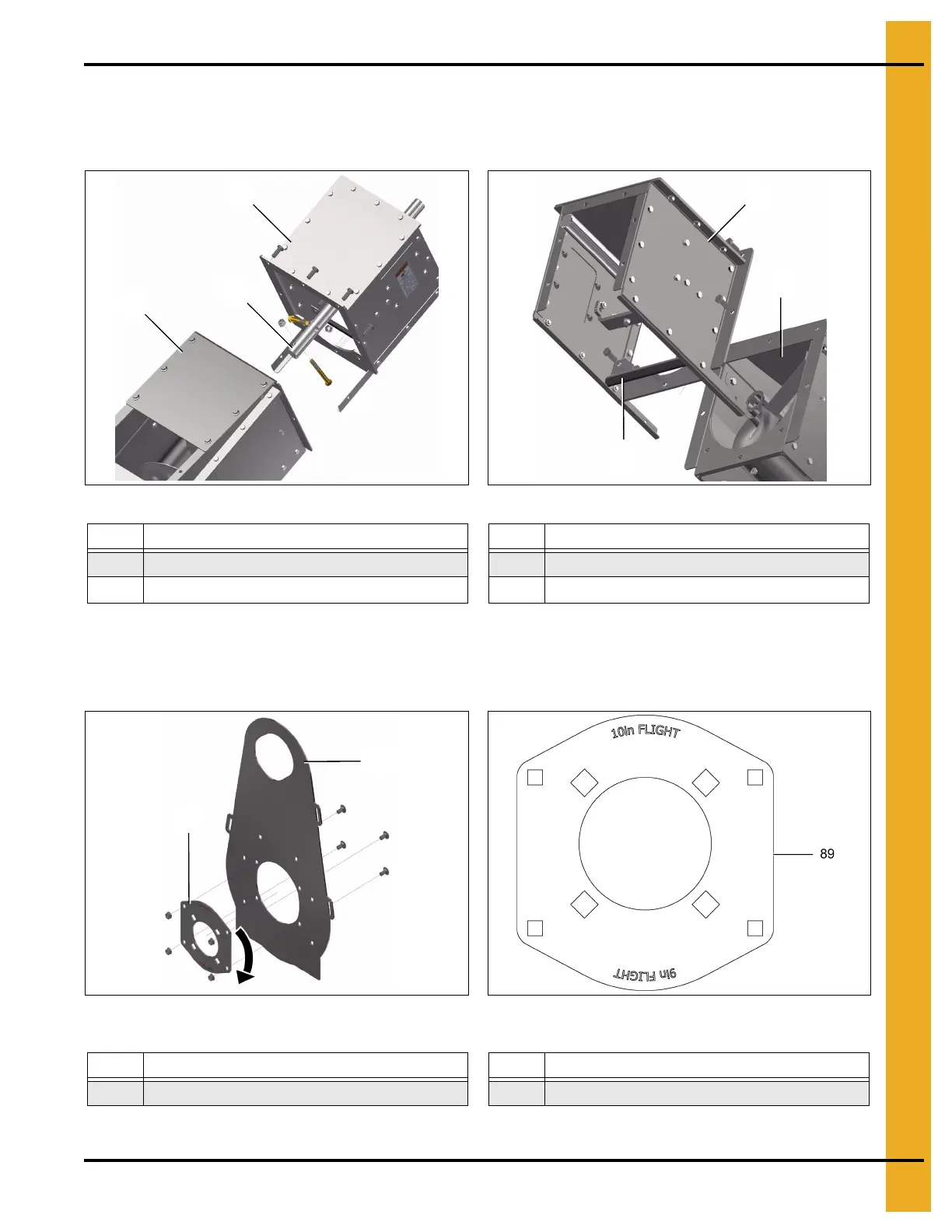
5. Bolt the powerhead (67) onto the end of the incline elbow assembly (84) with the eight bolts removed
previously. Ensure the discharge gate seal (81) is re-installed during this step. Insert the powerhead
shaft (76) into the incline flight bushing and secure it with two 3-1/2" bolts. (See Figure 4AV and
Figure 4AW.)
Figure 4AV Figure 4AW
6. Prepare polyshield plate assembly (65) for installation by un-bolting the bearing plate (89) and
rotate it 180°. Re-install the bearing plate (89). The words “10in FLIGHT” should now be upright.
(See Figure 4AX and Figure 4AY.)
NOTE: You can now proceed with typical powerhead installation as shown on Page 31.
Figure 4AX Figure 4AY Correct orientation of Bearing Plate for
Incline Elbow
7. Re-install the middle lid on the incline elbow, removed in Step 2 on Page 35.
Ref # Description Ref # Description
67 Powerhead 81 Discharge Gate Seal
76 Powerhead Shaft
84 Incline Elbow Assembly
Ref # Description Ref # Description
65 Polyshield Plate Assembly 89 Bearing Plate
 Loading...


