EasyManua.ls Logo

GST JB-QP-GST200 - User Manual

GST JB-QP-GST200
102 pages
Print Icon
To Next Page IconTo Next Page
Loading...
安装、使用产品前,请阅读安装使用说明书。
Read this manual carefully before installation and operation.
JB-QP-GST200 火灾报警控制器
安装使用说明书
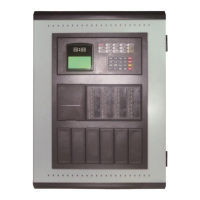
Intelligent Fire Alarm Control Panel
Installation and Operation Manual
Ver.1.08
Gulf Security Technology Co., Ltd

Table of Contents

Questions and Answers

  • M
    Michael RandolphAug 5, 2025
    What to do if the GST Control Panel shows an equipment fault?
    • K
      Kathy BrownAug 6, 2025
      If the GST Control Panel indicates an equipment fault, it could be due to the equipment being disconnected or damaged. Check the connection of the equipment. If the connection is secure, replace the faulty equipment.
  • R
    Randall NavarroAug 11, 2025
    Why is there no indication on my GST Control Panel, or why is the indication abnormal?
    • J
      Julie YoungAug 11, 2025
      The absence of any indication or an abnormal indication on the GST Control Panel can stem from several causes: a blown AC input fuse, an abnormal power supply, or a loose connection with the switchboard. To resolve this, replace the fuse if it's blown. Check and replace the low-voltage switch power if necessary. Also, check the connection to the display board to ensure it is secure.
  • M
    mccormickmichaelAug 15, 2025
    How to fix 'AC Fault' displayed on GST Control Panel after power-up?
    • D
      David EdwardsAug 15, 2025
      If your GST Control Panel displays 'AC Fault' after powering up, it may be due to no AC power or a blown AC fuse. Check and connect the AC wire to ensure power supply. If the wiring is correct, replace the AC fuse, referring to the specification on the label for the correct type.
  • T
    Travis HoffmanAug 21, 2025
    What to do if my GST Control Panel displays 'Bat Fault' after power-up?
    • R
      Robin BridgesAug 21, 2025
      If the GST Control Panel displays 'Bat Fault' after power-up, it indicates a problem with the battery. This could be due to a loose connection or a discharged/damaged battery. First, open the power box and check all battery connections. If the connections are secure, power up the panel for more than eight hours with the AC power supply. If the fault persists after charging, replace the batteries.
  • T
    Terry WrightAug 26, 2025
    Why is the GST Control Panel unable to register loop equipment?
    • C
      Colleen LeonardAug 26, 2025
      If the GST Control Panel is unable to register loop equipment, it may be due to a wrong bus or loose connection. Check the loop to ensure it is correctly wired and securely connected.
  • X
    xchapmanAug 31, 2025
    How to troubleshoot a loop fault on a GST Control Panel?
    • D
      Debbie JarvisAug 31, 2025
      A loop fault on the GST Control Panel usually indicates that the loop is shorted. To resolve this, check the loop wiring and repair any shorts you find.

Summary

Chapter 1 Product Introduction

1.1 Flexible Configuration and High Reliability

Highlights flexible configuration and high reliability of the FACP.

1.2 Zonal Signal Loop

Describes the zonal signal loop output ports for connecting fire alarm devices.

1.3 VDR Interface Available

Explains the RS485 communication ports for transmitting fire and fault signals to VDR.

1.4 Intelligent Operation, User-Friendly

Details the intelligent operation and user-friendly interface using shortcut keys.

1.5 Window-based, Menu-driven Display Interface

Describes the window-based and menu-driven display interface for clear information presentation.

1.6 Comprehensive Self-Testing Function

Explains the comprehensive self-testing function for internal and external devices.

1.7 Modular Switch Power Supply

Details the modular switch power supply with dual AC/DC inputs and battery backup.

Chapter 2 Construction and Components

2.1 Typical Configuration and Internal Structure Overview

Provides an overview of the external and internal structure of the FACP.

2.2 Description of Front Panel

Details the components of the FACP's front panel: display, indicators, and keypad.

2.3 Construction of Main Control Part

Describes the construction of the main control part, including main board, switch board, and LCD.

2.4 Power Supply System

Explains the FACP's power supply system, including main, standby, and emergency power.

2.5 Terminals

Details the external connection terminals of the FACP for various inputs and outputs.

Chapter 3 Installation and Commission

3.1 Open-package Inspection

Guides through the process of opening the package and checking its contents.

3.2 Installation Environment

Specifies the installation environment requirements and dimensions of the FACP.

3.3 Start-up Check

Details the initial power-up checks and system status verification.

3.4 Periphery Device Checking

Covers checking periphery device connections and their status.

3.5 System Connection and Setup

Explains system connection and setup procedures, referencing test tables.

3.6 Commission

Outlines the steps for commissioning the system after connection and setup.

3.7 Connect with Repeater Panel

Describes connecting the FACP to a fire display panel via RS-485.

Chapter 4 General User Operation Manual

4.1 Power-up, Power-down and Self-test

Details the procedures for powering up, powering down, and performing self-tests.

4.2 Keypad Operation

Explains general keypad functions, data input methods, and information viewing.

4.3 Unlocking and Locking the Keypad

Describes how to unlock and lock the keypad for security and operation.

4.4 Device Information Check

Guides on checking the registration status of devices connected to the system.

4.5 Message Display and Record

Covers how event information, operation results, and messages are displayed and recorded.

4.6 Sound Indication and Silence of the FACP

Explains the FACP's sound indications and how to silence them.

4.7 Silence and Start of Loop Sounders

Details silencing and starting loop sounders, and the related indicator lights.

4.8 Disposal of Fire Alarm and Fault Condition

Provides methods for handling fire alarms and system/field device faults.

4.9 Disabling and Re-enabling Devices

Describes how to disable and re-enable devices temporarily for maintenance.

4.10 User Setup

Explains user settings for print, start control, security, pre-alarm, project name, and language.

4.11 Reset Function

Describes the reset function, its capabilities, and how to perform it.

Chapter 5 Instructions for System Administrator

5.1 Modifying System Time

Guides on how to modify the system time, date, hour, minute, and second.

5.2 Modifying Password

Details password classification, modification, and user number assignment.

5.3 Device Definition

Explains how to define peripheral devices, including original code, user code, and type.

5.4 Programming Pre-alarm Condition

Describes how to program pre-alarm conditions by setting up device combinations.

5.5 EPS Set

Explains how to enable or disable the emergency power supply function of the FACP.

Chapter 6 System Commission

6.1 Entering and Exiting Commission State

Explains how to enter and exit the system's debugging state using a password.

6.2 Turning on The FACP in Commission State

Details the startup operations within the debugging state, including registration methods.

6.3 Operation in Commission State

Covers operations within debugging state: direct registration, commands, and bus debugging.

6.4 Device Registration Setup

Guides on setting up device registration, including external device registration.

6.5 Digital Command Operation

Explains how to send digital commands to bus devices and receive responses.

6.6 Commission of Loop Devices

Describes how to check communication status and real-time data of bus devices.

6.7 Modifying Device Features

Details how to modify original device codes or configurable properties.

6.8 VDR Action Setup

Explains how to set VDR actions for single or repeated transmission.

6.9 Restoring Factory Default

Describes how to restore factory default settings, clearing device definitions and modes.

Chapter 7 Troubleshooting and Maintenance

7.1 Troubleshooter

Provides a troubleshooting table for common problems and their solutions.

7.2 Regular Maintenance

Explains regular maintenance procedures, including LCD contrast adjustment.

Chapter 8 Caution

Appendix 1 Technical Specifications

Appendix 2 Device Type List

Appendix 5 Commission Check-off List

Appendix 6 Internal Connection Diagram

Appendix 7 VDR Interface Protocol

GST JB-QP-GST200 Specifications

General IconGeneral
BrandGST
ModelJB-QP-GST200
CategoryControl Panel
LanguageEnglish

Related product manuals