M
Melissa KingAug 6, 2025
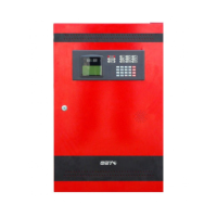
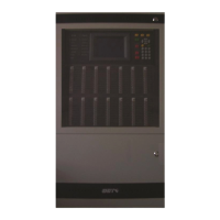
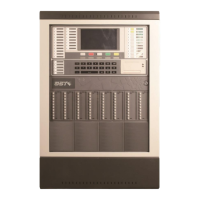
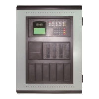
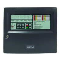
Why is there a battery fault on my GST GST102A Control Panel?
- JJohn ThomasAug 6, 2025
A battery fault on your GST Control Panel can occur due to several reasons: * A loose battery connection. In this case, check the cable connector. * A blown 5A fuse. If this is the case, replace the 5A fuse in the battery cable. * Low battery voltage. If the battery voltage is low, replace the batteries.