GST102A/GST104A/GST108A/GST116A
Conventional Fire Alarm Control Panel
Installation and Operation Manual
Page 10
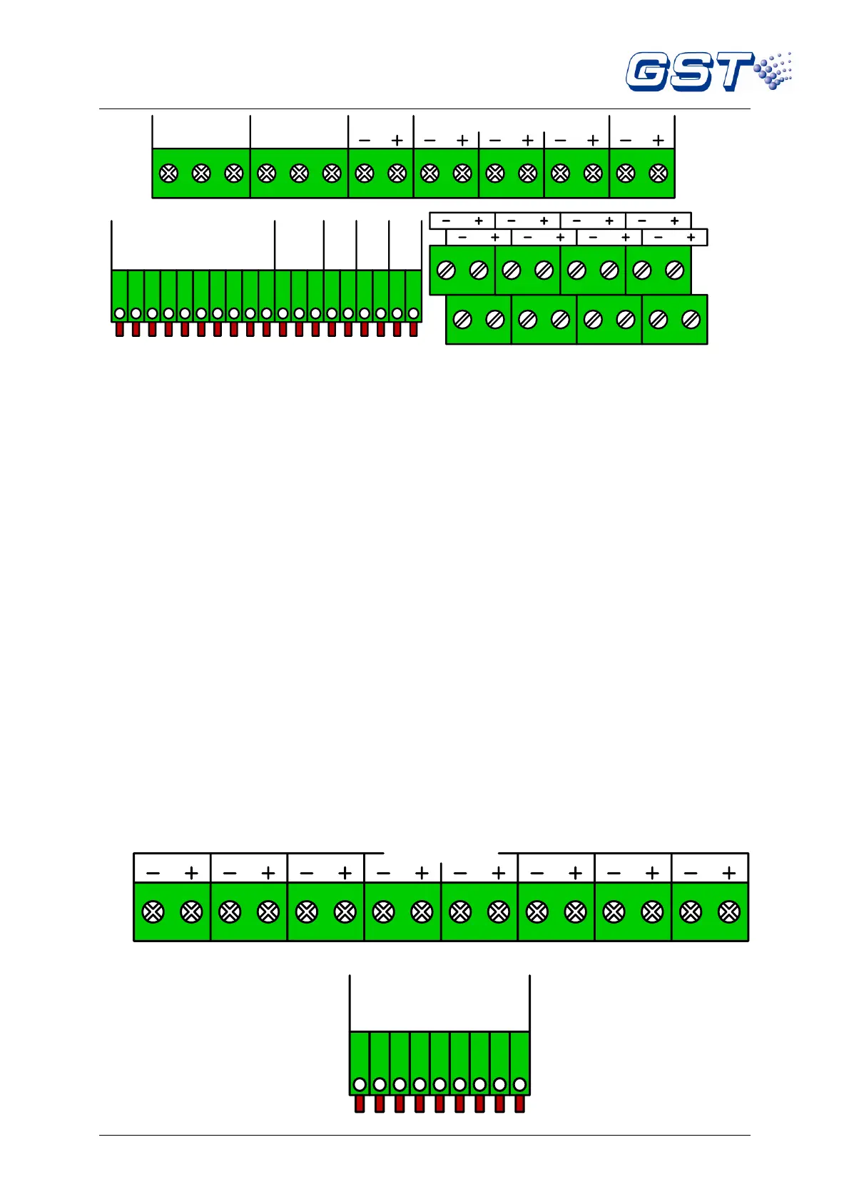
Fig. 1-4
FAULT (NC, COM, NO): Fault output terminal.
DIS. / SUP. (NC, COM, NO): Disable/supervisory terminal.
ALARM OUTPUT (-, +): Alarm output terminal.
SOUNDER OUTPUT (1~3) (-, +): Sounder output terminals.
AUX SUPPLY (-, +): Auxiliary power terminal.
REPEATER OUTPUT (Z1~Z8): Output terminals of repeater panel for zone 1 to 8.
FLT: Fault terminal for repeater panel connection.
FIRE: Fire alarm terminal for repeater panel connection.
MUTE: Mute terminal for repeater panel connection.
0V: Power supply negative terminal for repeater panel connection.
PW ON: Reserve terminal for repeater panel connection.
RESET INPUT: For remote operation of reset.
EVAC INPUT: For remote operation of EVAC.
SILENCE INPUT: For remote operation of silence.
ZONE INPUT (1~8): Zone 1 to 8 input terminals.
1.5.2 Terminals on Extension Board
Note: The contents of italics are not covered in EN54-2/4.
Terminals on the extension board are shown in Fig. 1-5 and Fig. 1-6.
 Loading...