GST102A/GST104A/GST108A/GST116A
Conventional Fire Alarm Control Panel
Installation and Operation Manual
Page 11
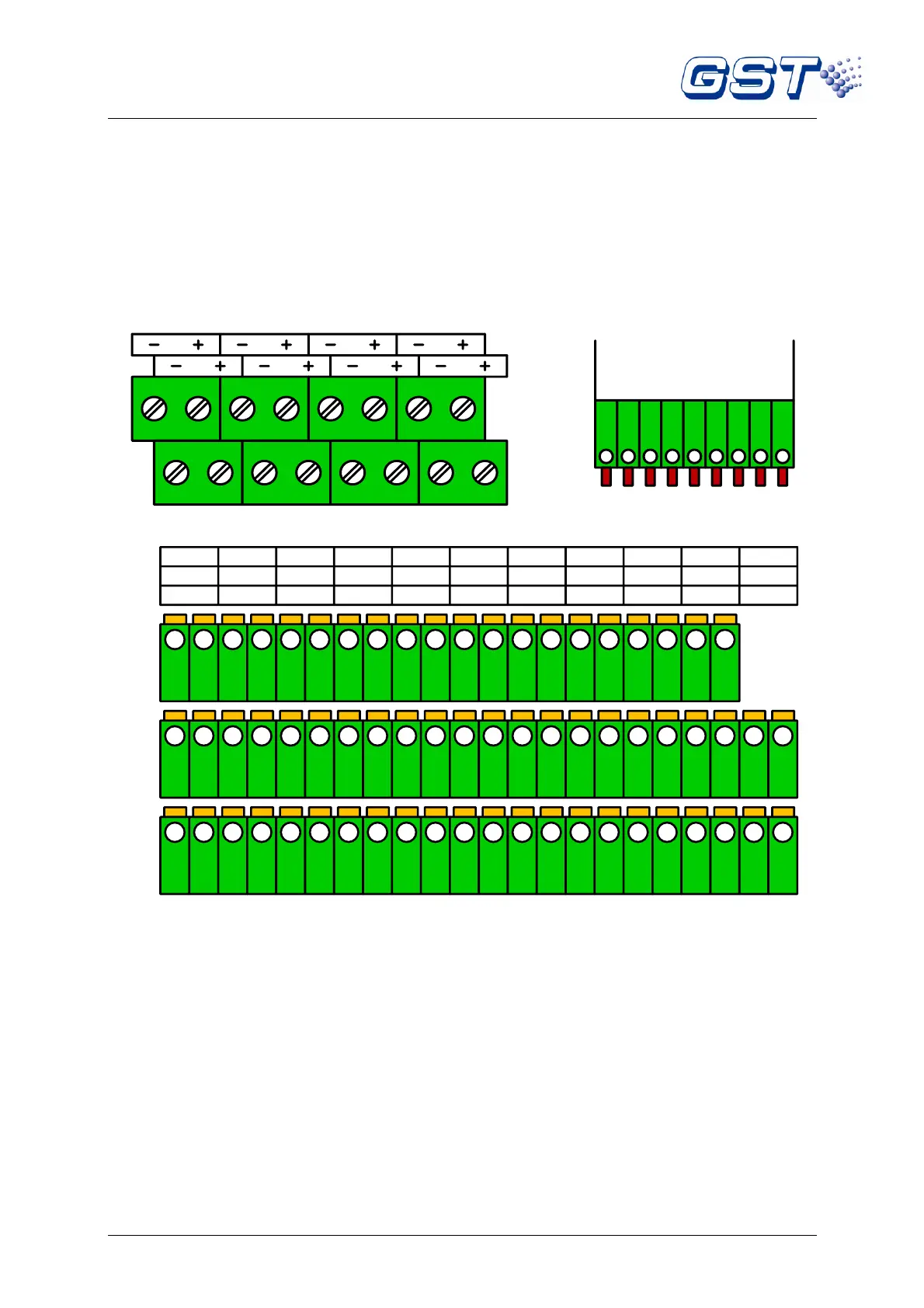
Fig. 1-6
ZONE INPUT (9~16): Zone 9 to 16 input terminals.
Z9~Z16: Output terminals of repeater panel for zone 9 to 16.
0V: Power supply negative terminal for repeater panel connection.
1.5.3 Terminals on Relay Board of RB116A
Note: The contents of italics are not covered in EN54-2/4.
Terminals on relay board of RB116 are shown in Fig. 1-7 and Fig. 1-8.
Fig. 1-8
ZONE INPUT 9~16: Zone 9 to 16 input terminals.
Z9~Z16: Output terminals of repeater panel for zone 9 to 16.
0V: Power supply negative terminal for repeater panel connection.
FAULT1~FAULT16: Fault output terminals for zone 1 to 16.
ALARM1~ALARM16: Alarm output terminals for zone 1 to 16.
1.5.4 Terminals on Relay Board of RB108A
Terminals on relay board of RB108A are shown in Fig. 1-9. Relay board of RB104A/RB102A is
similar to RB108A with fewer terminals.