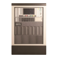
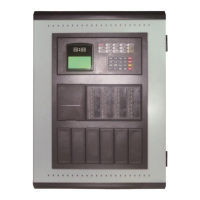
GST102A/GST104A/GST108A/GST116A
Conventional Fire Alarm Control Panel
Installation and Operation Manual
Page 19
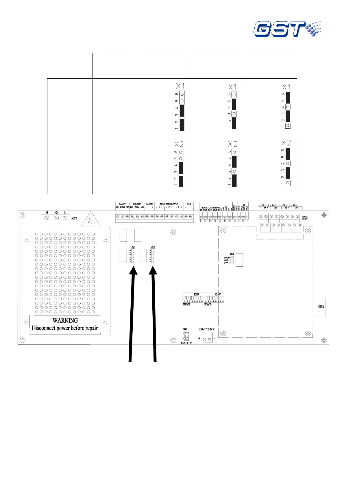
Table 3-5
X1 X2
Fig. 5
3.3 Disablement of a Zone or Output
3.3.1 Use of Disablement Function
In case there is any fault with a detection zone or a sounder/alarm output, it can be disabled so that
it does not affect normal operation of other zones. After the fault is removed, the disabled detection
zone or output can be enabled again. This operation applies to the 16 detection zones, 3 sounder
outputs, and 1 fire alarm output.