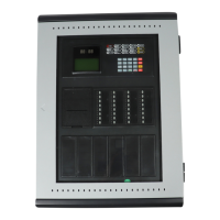
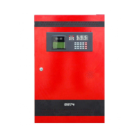
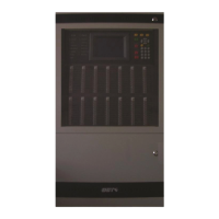
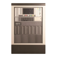
GST102A/GST104A/GST108A/GST116A
Conventional Fire Alarm Control Panel
Installation and Operation Manual
Page 23
☆☆☆☆☆☆☆☆☆☆☆☆☆☆☆☆☆☆☆☆☆☆☆☆☆☆☆☆☆☆☆☆☆☆☆☆☆☆☆☆☆☆
Note: If one of the outputs (sounder outputs or alarm output) is programmed with delay, then there
should be at least one zone set as “With Manual Call Point” to ensure the delay could be
overrode for immediate output.
Note: The zone “with manual call point” can override all delay functions.
Note: Every zone is default set “With Manual Call Point”.
☆☆☆☆☆☆☆☆☆☆☆☆☆☆☆☆☆☆☆☆☆☆☆☆☆☆☆☆☆☆☆☆☆☆☆☆☆☆☆☆☆☆☆
3.5.2 Setting Associated Sounders to a Zone
Programming steps of zone association output setting are shown below.
1 Enter access level III.
2 Set the “4” of SW2 (SOUNDER OUTPUT) on control board to ON position.
3 Pressing the OUTPUT PROGRAM button, OUTPUT PROGRAM LED illuminates steadily and
the amber LED of zone 1 flashes to show zone 1 is to be selected for setting up associated
sounders. The FAULT LED will indicate according to the CIE fault condition. Other indicators,
except for the above mentioned LEDs, will be turned off.
4 Pressing the SCROLL button toggles between zones 1 to 16.
5 Press the OUTPUT PROGRAM button again to set up its associated Sounder Outputs. The
SOUNDER X FLT/DIS LED flashes, showing Sounder Output 1 has been selected for setup.
6 Pressing the SCROLL button to select sounder output 1, 2 or 3.
7 Pressing the DISABLE/ENABLE or TEST button can respectively switch on or off their
indicator. The DISABLE/ENABLE LED and TEST LED are used for setting up the output state
of the selected Sounder Output to be an Immediate, Delayed or No Output, refer Chapter 3-5-
4, Table 3-6.
8 Set the “5” of SW2 (SOUNDER MODE) ON or OFF to change the sound pattern of the selected
Sounder Output to be continuous or pulse, refer Chapter 3-5-4, Table 3-7.
9 The Dip switches “1” to “4” of SW3 (DELAY TIME) are used for setting the delay time of the
selected Sounder Output from 0-150 seconds, refer Chapter 3-5-4, Table 3-8.
10 Pressing the ENTER button saves the current settings for SOUNDER X and the CIE will sound
for 1 second to indicate the successful setup. Set the “5” of SW2 (SOUNDER MODE) and “1”
to “4” of SW3 (DELAY TIME) to OFF position. Repeat steps 6 to 10 to program another
Sounder Output for this zone.
11 Press the CANCEL button to exit the programming of this zone and return to the zone selection
(step 4). Repeat steps 4 to 10 to program other zones.
12 At the zone selection step, pressing the CANCEL button again will exit programming mode.
And OUTPUT PROGRAM LED will turn off.
13 Set the “4” of SW2 (SOUNDER OUTPUT) to OFF position.
14 Exit access level III.