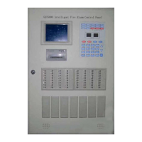
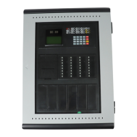
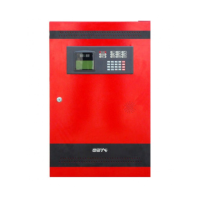
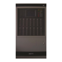
GST102A/GST104A/GST108A/GST116A
Conventional Fire Alarm Control Panel
Installation and Operation Manual
Page 18
Chapter 3 System Setup
3.1 Setting Access Levels
The CIE provides three access levels:
Level I, for anybody to silence the buzzer by pressing Mute/ACK key.
Level II, for a fire warden or fire brigade personnel to disable, test, reset the panel, silence
the buzzer, silence/resound the sounder outputs, evacuate the building and so on.
Level III, Used by fire service maintenance companies for the programming of various
output modes.
3.1.1 Setting Access Level I
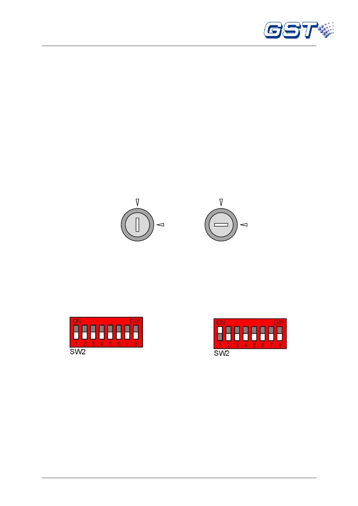
Turning CONTROL ENABLE lock to “OFF” shown as in Fig. 3-1, the CIE is set to access level I.
Please be aware dip switch number 1 of SW2 (LEVEL 3 Access Mode) on the control board should
also be in the OFF position as shown in Fig. 3-3.
Fig. 3-1 Fig. 3-2
3.1.2 Setting Access Level II
Turning CONTROL ENABLE lock to “ON” shown as in Fig. 3-2, the CIE is set to access level II.
Please be aware dip switch number 1 of SW2 (LEVEL 3 Access Mode) on the control board should
also be in the OFF position as shown in Fig. 3-3.
Fig. 3-3 Fig. 3-4
(White cell indicates the position of switch)
3.1.3 Setting Access Level III
If “1” of SW2 (LEVEL 3) is set to ON position as shown in Fig. 3-4, whichever position the Control
Enable lock is, the CIE is set to access level III.
3.2 Setup of the Sounder / Alarm Output
Sounder Output 1 and alarm output can be set through Pins for three output modes: voltage output,
normally open contact output and normally closed contact output. The default setting for alarm
output is a normally open contact output. The default setting for Sounder Output 1 is a 24VDC
voltage output.
Sounder Outputs 2 and 3 only have 24VDC voltage output modes.
Alarm Output (X1) and Sounder Output 1 (X2) are set as shown in Table 3-5.