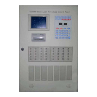
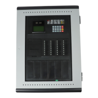
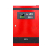
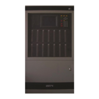
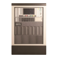
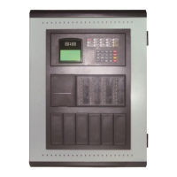
GST102A/GST104A/GST108A/GST116A
Conventional Fire Alarm Control Panel
Installation and Operation Manual
Page 26
3.6 Supervisory Mode
3.6.1 Use of Supervisory Function
Zones can be defined as supervisory for monitoring field device status.
☆☆☆☆☆☆☆☆☆☆☆☆☆☆☆☆☆☆☆☆☆☆☆☆☆☆☆☆☆☆☆☆☆☆☆☆☆☆☆☆☆☆☆
Note: Supervisory setting will be saved even if the CIE is powered off.
Note: Supervisory function has not been tested for EN54-2.
☆☆☆☆☆☆☆☆☆☆☆☆☆☆☆☆☆☆☆☆☆☆☆☆☆☆☆☆☆☆☆☆☆☆☆☆☆☆☆☆☆☆☆
3.6.2 Programming a Zone to Supervisory
1 Enter access level III.
2 Set the “8” of SW3 (RESERVE USE) on control board to ON position.
3 Pressing the OUTPUT PROGRAM button, OUTPUT PROGRAM LED illuminates steadily and
the green LED of zone 1 starts flashing to show zone 1 is to be selected for supervisory setup.
SUPERVISED LED and SOUNDER 1 FLT/DIS flashes. The FAULT LED will indicate according
to the CIE fault condition. Other indicators, except for the above mentioned LEDs, will be
turned off.
4 Pressing the SCROLL button can toggle between zones 1 to 16. Flashing Green zone LED
indicates the selected zone. A steady illuminating green zone LED indicates the zone is already
defined as a supervised.
5 Pressing the TEST button can switch among the LED indicators Sounder 1, Sounder 2,
Sounder 3 and Alarm Output. options as shown in table 3-9
Table 3-9
6 Pressing the DISABLE/ENABLE button to turn LED ON or OFF of selected indicator. Default
setting are all LED’s are OFF.
7 Pressing the ENTER button to set the zone as supervised with programming logic or cancel
existing supervised zone logic, and the CIE will give 1 second sound indication. Repeat step
4 to 7 to set another zone as supervised.
8 Pressing the CANCEL button exits supervisory setting status and OUTPUT PROGRAM LED
turns off.
9 Set the “8” of SW3 (RESERVE USE) on control board to OFF position.
10 Exit access level III.