GST102A/GST104A/GST108A/GST116A
Conventional Fire Alarm Control Panel
Installation and Operation Manual
Page 9
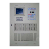
Display board: For information display and key operation.
Relay board (optional): Providing detection input and repeater output for zone 9 to 16.
Controlling outputs of alarm relay and fault relay for zone 1 to 16.
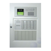
1.4.3 Configuration and Functions of GST-108A
GST-108A control panels have the following configuration and functions.
Batteries: Standby power source for the CIE.
Control board: For controlling power supply, charger, and all outputs such as
fault/disable/supervisory relay output, alarm output, sounder outputs and repeater panel
for zone 1 to 8, and monitoring the state of zone 1 to 8.
Display board: For information display and key operation.
Relay board (optional): Controlling outputs of alarm relay and fault relay for zone 1 to 8.
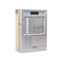
1.4.4 Configuration and Functions of GST-104A.
GST-104A control panels have the following configuration and functions.
Batteries: Standby power source for the CIE.
Control board: For controlling power supply, charger, and all outputs such as
fault/disable/supervisory relay output, alarm output, sounder output and repeater panel for
zone 1 to 4, and monitoring the state of zone 1 to 4.
Display board: For information display and key operation.
Relay board (optional): Controlling outputs of alarm relay and fault relay for zone 1 to 4.
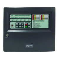
1.4.5 Configuration and Functions of GST-102A
GST-102A control panels have the following configuration and functions.
Batteries: Standby power source for the CIE.
Control board: For controlling power supply, charger, and all outputs such as
fault/disable/supervisory relay output, alarm output, sounder outputs and repeater panel
for zone 1 to 2, and monitoring the state of zone 1 to 2.
Display board: For information display and key operation.
Relay board (optional): Controlling outputs of alarm relay and fault relay for zone 1 to 2.
1.5 Terminal Description
1.5.1 Terminals on the Control Board
Note: The contents of italics are not covered in EN54-2/4.
Terminals for batteries are shown in Fig. 1-3.
 Loading...