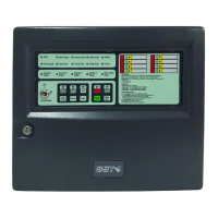
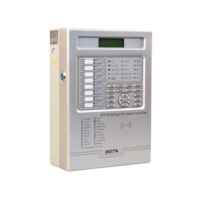
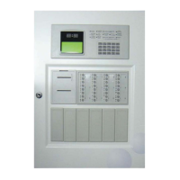
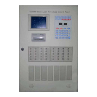
GST102A/GST104A/GST108A/GST116A
Conventional Fire Alarm Control Panel
Installation and Operation Manual
Page 4
☆☆☆☆☆☆☆☆☆☆☆☆☆☆☆☆☆☆☆☆☆☆☆☆☆☆☆☆☆☆☆☆☆☆☆☆☆☆☆
Note: External overcurrent protection device is required and should be installed
near the equipment.
☆☆☆☆☆☆☆☆☆☆☆☆☆☆☆☆☆☆☆☆☆☆☆☆☆☆☆☆☆☆☆☆☆☆☆☆☆☆☆
1.2.2 Batteries
Minimum Operating Voltage: 21.5V
Maximum Charging Current: 400mA
Maximum Charging Voltage: 27.6V
Battery Type: Sealed lead-acid battery
Minimum Batteries: 2 batteries, 7Ah/12VDC
Recommended Battery and Model: Yuasa NP7-12
Standby battery maximum operating current: 2.5A
Standby battery current with full-loaded: 0.1A
Maximum Internal Resistance: 1.0Ω
1.2.3 Load of Power Supply
The maximum output current in standby condition is 550mA (Max. a as described in Table
1 of EN 54-4 Clause 9.2.1.)
The maximum output current in alarm condition is 2.35A (Max. b as described in Table 1
of EN 54-4 Clause 9.2.1).
The Minimum output current in fully charged condition is show in Table1-3 (I Min. as
described in Table 1 of WN54-4 Clause, 9.2.1)
Table 1-3
1.2.4 Detection Zone
The control panel supports up to 16 detection zones, and the number of external conventional
detectors in each zone reaches 32, with the following parameters:
Loop Voltage: 15VDC~28VDC
Maximum output current per zone
: 170mA.
Dynamic Current: Resistance range for fire alarm is 150
Ω
~1.5k
Ω
(normally 470
Ω
), using
a 4.7k
Ω
end of line resistor or AEOL (active end of line unit). The alarm current for a zone
depends on the number of conventional devices in the zone. The alarm current for a
conventional detector is about 25mA.
Maximum output current for the 16 detection zones is 400mA.
Recommended Wiring: 1.0mm
2
or above 2 core cable, complying with local installation
codes.
Recommended Cable Length: no more than 1000m
1.2.5 Output Interface
Fault Output
➢ Type: normally open/close contact output