Pressure Build-Up (Thermal Expansion)
During the heating cycle of the water heater, the water
expands creating a pressure build-up in the plumbing sys-
tem. If the pressure exceeds 150 psi, water will come out of
the Temperature-Pressure (T&P) Relief Valve. This is a nor-
mal safety function of the T&P valve. The water supply
meter may have a check valve or back flow preventer
inside. This can increase the possibility of pressure build-
up. Causes of discharge can be thermal expansion, excess
system pressure, too high a temperature setting on the ther-
mostat or something in the water heater causing excess
temperatures in the heater.
Thermal Expansion
As water is heated, it expands (Thermal expansion). In a
closed system the volume of water will grow when it is heat-
ed. As the volume of water grows there will be a correspon-
ding increase in water pressure due to thermal expansion.
Thermal expansion can cause premature tank failure (leak-
age). This type of failure is not covered under the limited
warranty. Thermal expansion can also cause intermittent
T&P valve operation: water discharged from the valve due
to excess pressure build up. This condition is not covered
under the limited warranty. The T&P valve is not intended
for the constant relief of thermal expansion. A properly sized
and charged thermal expansion tank must be installed on all
closed systems to control the harmful effects of thermal
expansion. To prevent the T&P valve from discharging hot
water there are two (2) recommendations:
OPTION 1:
Install a 125 psi Pressure Relief (only) valve in
the cold water supply line. Make sure that the discharge of
this valve is directed to a drain to prevent water damage and
it is protected from freezing,
OR
OPTION 2:
Install an expansion tank on the cold water sup-
ply line. For every 50 U.S. gallons of stored water, the
expansion tank must have a minimum capacity of 1.5 U.S.
gallons. Contact a local plumbing service agency to have a
thermal expansion tank installed.
Electrical
DO NOT apply power to this unit until it is completely filled
with water.
1. Check to see that the element marking and nameplate
data correspond with the electric service available. The
junction box where electrical connections are made is
located near the top of the heater, near the upper
access door.
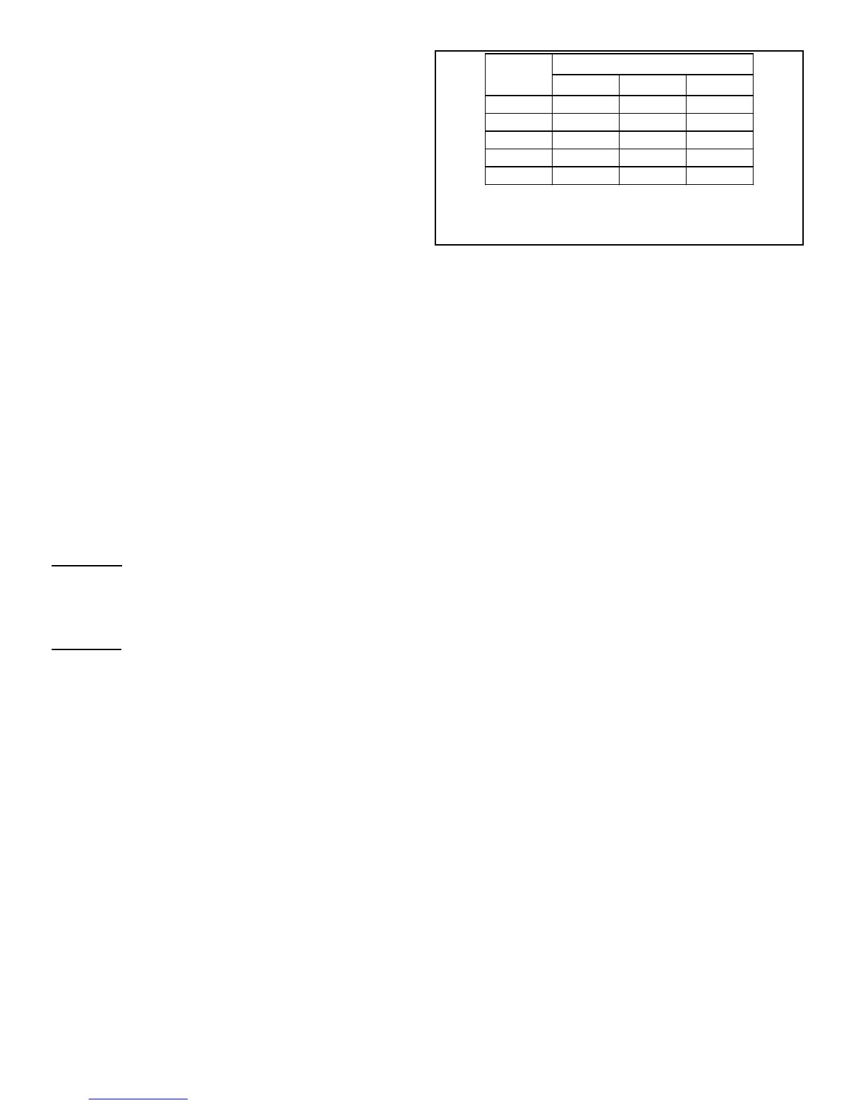
2. Install a circuit directly from the main fuse box. This cir-
cuit must be the right size for the length of run and the
load (see Table 1).
3. A ground wire must run from the green ground screw
provided at the electrical connection point in the heater
junction box to the ground connection at the service
panel.
4. Adequate fusing must be provided at the service
entrance as required by local codes and/or electric util-
ity having jurisdiction. This can be accomplished with
either a circuit breaker or fuse block in the service panel
or a separate disconnect switch, so that electric power
can be shut off easily when working on the heater.
5. Final connections are made at the junction box in the
heater. Access to the junction box is obtained by remov-
ing the cover near the knockouts.
6. The heater you have received is internally wired. A spe-
cific wiring diagram is located inside the upper door or
for certain models on the rating plate. All wiring is
colour-coded and connections must be made as shown
in the wiring diagram.
Wiring
TWO WIRE CIRCUIT FOR NON-SIMULTANEOUS OPER-
ATION. SINGLE HIGH LIMIT.
The basic operation of a two-thermostat system (upper and
lower) on an electric water heater of 240 volts is as follows:
Only one element will come on at any one time. This is
known as a flip/flop system. On a 240 volt water heater,
there will always be 120 volts to both elements. The ther-
mostat will direct the second leg of the 120 volts to the ele-
ment to complete the 240 volts required for energizing the
element.
Initial Start Up: When the tank is full of cold water, the
upper thermostat will take priority and the top portion of the
water will heat up to the setting of the thermostat. Once that
temperature has been reached, the thermostat will then flip
down the 120 volts to the lower thermostat. The thermostat
switch closes and the bottom portion of the tank heats up
until the water reaches the setting on that thermostat. At this
point the tank will be full of hot water.
Normal Operation: When hot water is being used, cold
water enters the bottom of the heater (either bottom feed or
by diptube), and the bottom element will begin to heat the
cold water. If lots of hot water has been used, the upper
thermostat will take priority and the top portion of the heater
will be heated. Once heated, the thermostat will flip down to
the lower thermostat to heat the lower portion.
 Loading...