APS-'1.701
&
APT-9501U
&
APS
-
9102
cer'q
Manual
APS
-
9301
&
APS-9501U
&
APS
-
9102 ser's hlaiiual
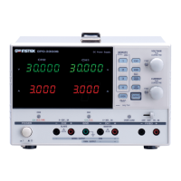
4.
Panel
Description
(I
)
'ALARM RESET' Kej
Rect ke\ to cease the buzz and reqet the output.
(2)
'SIR'
Key
Sa.
e
01
Recall funct~on selectin2 key
(3
SAVEIRECALL indicator
111 the mode to save setting. the indicator doesn't light. In the mode to
recall setting. the indicator liphts.
($1
.ii
I
.(2
1).
(22)
'MEMI' 'MEM2' 'MEM3' 'MEM4' keys
W-l.eri the
S.WE/RECALL
indicator is off. the four keys are for saving
four different settings. When
the indicator are on. the keys are for
reclllin: the saved settings.
(6
1.1
23
\
'SOHz',
'60Hz'Keys
Ore
touch key for
50Hz
and 60Hz output
I
-
espectively.
(71
Output Frequency LED Display:
If
,he 'OUTPUT' key isn't pressed. the indicator doesn't light, and the
setiinp fi-equency value will be displayed on the output frequency LED
displaj-. Tf the 'OUTPUT' key is pressed. the indicator light, and the
auiput frequency value will be displayed on the output frequency LED
di.;pla~-.
18).(21).
'A'
m'v'
Kej-s
Th:
tn-c.
ke)-s are for frequency setting, to increase or decrease the
fl.er]uency value respectively every time they are pressed. The adjusting
rate depend< on the
'COARSE'
key arid the frequency value itself.
i9!
Coarse Indicator
If
the coarse adjustment mode is selected. the coarse indicator will light.
If t:le fine adjustment mode is selected. the coarse indicator does not light.
il0)High
/
T,ow Range Indicator of Outputvoltage
if
tiiis indicator lights. the output voltage is in the range
0
-
300V.
If this
Tn?icntor does not light. the output voltage is in the range
0
-
150V.
(
1
1
127)
'
110\
'.
'
220\
'
Keys
Onc
touch he? fn~
220V
and IIOV output respect~vely
(12)Output Voltage LED Display
If the
'OUTPUT'
Key is not pressed. the indicator doesn't light. and the
setting value will be displayed on the OutputVoltage LED Display. If the
'OUTPUT'
key is pressed, the indicator lights. and the output value
\dl
be
displayed on the Output Voltage LED
Displa!-.
(13).(28).
'A'.
'V'
keys
The two keys are for voltage setting. to increase or decrease the \-oltage
value respecti\~ely every tinie the!. al-e pressed. The adjusting rate depends
on the
'COARSE'
key.
(14)Function of Ammeter Indicator
If ammeter's indicator lights. the
\.slue
of
output current will be displayed
On the
rnultimeter LED display.
(1S)Function of Wattage Meter Indicator
If wattage meter's indicator liflits. the
\slue
of output wattage will be
displayed on the
~nultimeter LED display.
(16)
Multinieter LED Display
The value of output cul-rent. wattage or po\T'er factor \%:ill be displa!.ed
hy
respective key from
'A'.
'I?''.
to
'PF'.
(17) Function of Power Factor Meter Indicator
If powel. factor meter's indicator light<. the value of output power factor
will be displayed
on the multirneter. LED display.
(1
8)
'OUTPUT' Key
Output function enabledldisabled selection key.
(
19)Output Indicator
When output is enabled. the output indicator \%.ill li_gl?t.
(20)Power Switch
To turn on /off APS9301/9501
(25)
'
COARSE
'Key
CoarselFine adjustment selection key.
(26)
'
RANGE
'
Key
For the high /low output voltage's ran,oe selection.
Artisan Technology Group - Quality Instrumentation ... Guaranteed | (888) 88-SOURCE | www.artisantg.com
 Loading...