DUAL DISPLAY DIGITAL MULTIMETER
USER MANUAL
12
in a place where ambient temperature exceeds 50℃.
DUAL DISPLAY DIGITAL MULTIMETER
USER MANUAL
13
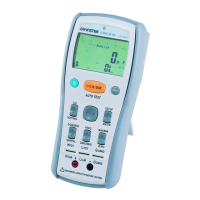
4. OPERATION INSTRUCTIONS
4-1. Front panel and rear panel
The front panel, shown in Figure4-1, contains three main elements: the
input terminals, the primary and secondary displays, and the push
buttons. The rear panel, shown in Figure 4-2, contains the AC
power-line connector, and fuse & line voltage selector, input fuse
holder, and interface terminal.
4-2. The [SHIFT] key and function keys
[SHIFT] button is used to enable the secondary function of certain
function keys that with blue symbols printed above. The SHIFT LED
will be on after pressed the [SHIFT] button. At this time, only the
buttons with blue symbols are workable. To release SHIFT function,
press [SHIFT] again. For example, to select DCmV function, press
[SHIFT], then press [DCV] ([DCmV]).
4-3. Set mode
Press [SHIFT] [SET] in sequence into SET mode, then proceed further
setting by pressing the white characters with blue background [HI],
[LO], [REF Ω], [RS232], [GPIB], [ENTER] sequentially.
4-4. Warm up
The instrument requires half-an-hour warm up to achieve rated
accuracy.
4-5. Over-range indication
An input is over-range if it exceeds the full scale of the selected range.
GDM-8246 indicates an input is over-range by lighting the “—OL—”
pattern on display.
4-6. No specification indication
On AC+Hz measured mode, when an input is less sensitivity, the
secondary display show “————”. When the frequency of an input
exceeds 110kHz, the primary display will show “————”.

 Loading...