MULTI-OUTPUT POWER SUPPLY
USER MANUAL
4
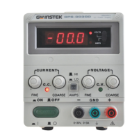
(4) Output current : 1A
MULTI-OUTPUT POWER SUPPLY
USER MANUAL
5
2-9. Insulation
Between chassis and output terminal : 20MΩ or above (DC 500V).
Between chassis and AC cord : 30MΩ or above (DC 500V).
3. THEORY OF OPERATION
The power supply consists of an AC input circuit and transformer; a bias
supply consisting of an rectifier, filter, pre-regulator and reference voltage source;
a main regulator circuit consisting of the main rectifier and filter, a series regulator,
a current comparator, a voltage comparator, a reference voltage amplifier and a
relay control circuit. The circuit element consists of integrated circuit U101, U102,
U103, U104, U105, U108.
The circuit arrangement is shown as block diagram in Fig. 3-1. The circuitry is
discussed with reference to the block diagram function description. Single phase
input power is applied to transformer through the input circuit.
Auxiliary rectifier D1021~1024 provides a bias voltage, filtered by capacitor
C103, C104 for the preregulator. U101, U108 that provides a regulator voltage for
elements of action.
The main rectifier, a full wave bridge rectifier provides the power which is
filtered by capacitor, C1021 and then regulated via a series regulator and delivers
to the output.
U105 acts as a current limiter. When current is over predetermined rating it is
activated and decreases the current.
U102 provides a reference voltage for U103, U105.U103 is an inverter
amplifier.U104 is a comparator amplifier which compares reference voltage and
feedback voltage, and then delivers to Q103, Q104, which then calibrates the
output voltage.
Q113 is activated when the unit is overload. It controls Q103 current
magnitude which limits the output current.
The relay control circuit provides limited power dissipation in series regulator.
 Loading...