MULTI-OUTPUT POWER SUPPLY
USER MANUAL
8
Fig. 4-2 Real Panel
MULTI-OUTPUT POWER SUPPLY
USER MANUAL
9
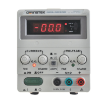
4-1. Front Panel
(1) Power switch : ON/OFF the power input.
(2) Meter V : Indicated the CH1 or CH3 output voltage.
(3) Meter A : Indicates the CH1 or CH3 output current.
(4) Meter V : Indicates the CH2 or CH4 output voltage.
(5) Meter A : Indicates the CH2 or CH4 output current.
(6) Voltage Control : Adjust the output voltage of the CH1 supply, and as the
adjustment control for the maximum output voltage of the
CH2 supply when either parallel or series tracking operation.
(7) Current Control : Adjust the output current of the CH1 supply, and as the
adjustment control for the maximum output current of the
CH2 supply when either parallel or series tracking operation.
(8) Voltage Control : Adjust the output voltage of the CH2 supply when in
independent operation.
(9)
(10)
(11)
(12)
(13)
Current Control
Voltage Control
Voltage Control
CH1/CH3
selects switch
CH2/CH4
selects switch
: Adjust the output current of the CH2 supply.
: Adjust the output voltage of the CH3 supply (invalid for
GPS-2303&3303).
: Adjust the output voltage of the CH4 supply (invalid for
GPS-2303&3303).
: Select CH1 or CH3 output voltage or current (invalid for
GPS-2303&3303).
: Select CH2 or CH4 output voltage or current (invalid for
GPS-2303&3303).
 Loading...