g,
@ O
'5
O
For
motor
location
,^11
I39.A^
&t
battery
connector
SLOPE
GLIDER
VERSIONS
SPITFIRE
42.„..
::i
•
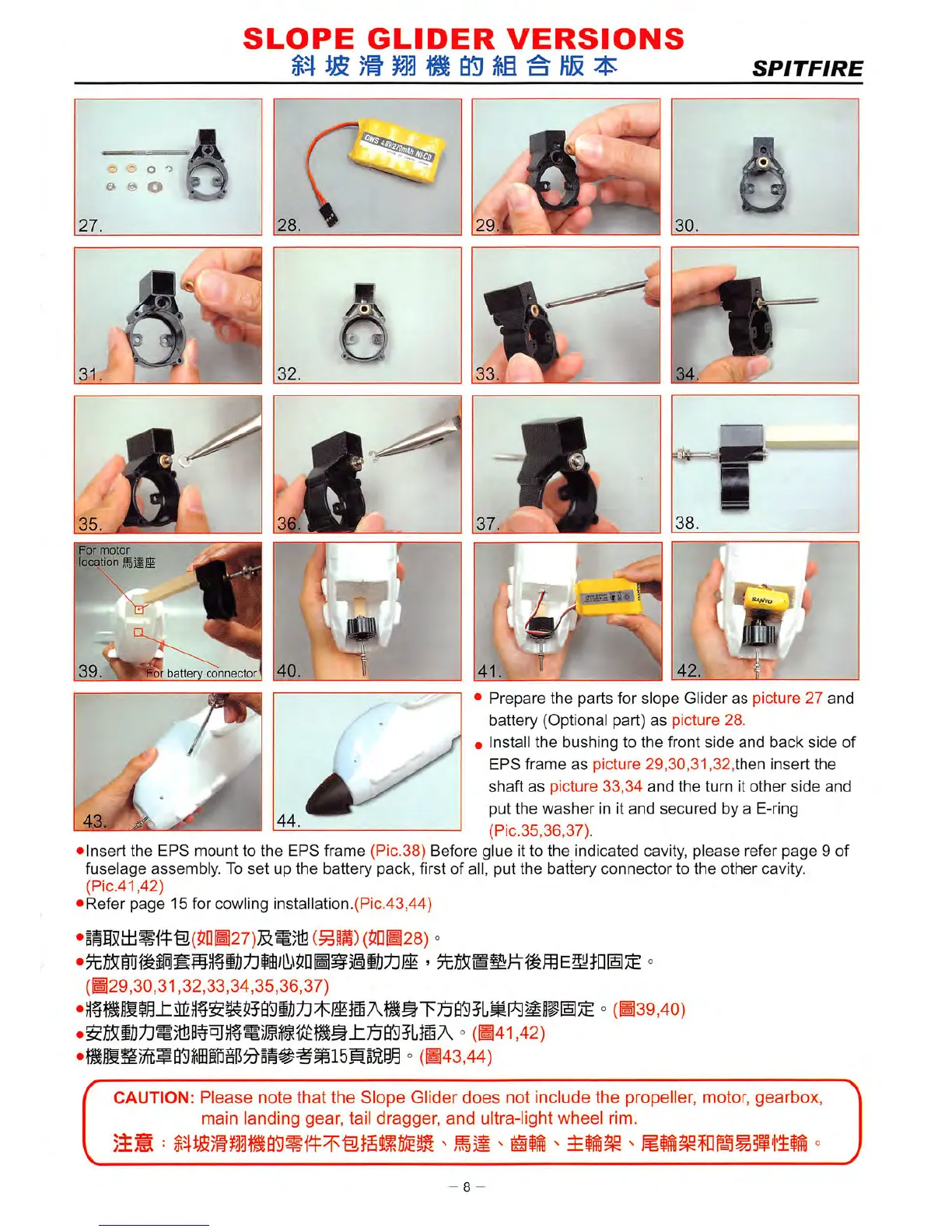
Prepare
the
parts
for
slope
Glider
as
picture
27
and
battery
(Optional part)
as
picture
28.
• install
the
bushing
to
the
front
side
and
back
side
of
EPS
frame
as
picture
29,30,31,32,then
insert
the
shaft
as
picture
33,34
and
the
turn
it
other
side
and
put
the
washer
in it
and
secured
by a E-ring
(Pic.35,36,37).
• insert
the
EPS
mount
to
the
EPS
frame
(Pic.38) Before glue it to
the
indicated cavity,
please
refer
page
9 of
fuselage
assembly.
To
set
up
the
battery
pack,
first of all,
put
the
battery
connector
to
the
other
cavity.
(Pic.41,42)
•
Refer
page
15
for cowling
installation.(Pic.43,44)
•iiI5tli«f^®(5PB27)SS)tfi
(^li)
(5nB28) °
(H29,30,31,32,33,34,35,36,37)
°
(B39,40)
° (B41,42)
° (B43,44)
CAUTION:
Please
note
that
the
Slope
Glider
does
not
include
the
propeller, motor,
gearbox,
main
landing
gear,
tail
dragger,
and
ultra-light
wheel
rim.
8 -