EasyManua.ls Logo

Gyems RMD-X - User Manual

Gyems RMD-X
21 pages
Print Icon
To Next Page IconTo Next Page
Loading...
光毓机电 RMD-X8
V1.0
1
RMD-X User Manual For Motion Actuator
CATALOGUE
1 PRODUCT INTRODUCTION .................................................................................................. 3
1.1 NAMING RULES ...................................................................................................................................................... 3
1.2 FEATURES ................................................................................................................................................................ 3
1.2.1Control Mode ............................................................................................................................................. 3
1.2.2Communication Control Mode ........................................................................................................... 3
1.2.3Encoder Feedback .................................................................................................................................... 4
1.2.4Technical Highlights................................................................................................................................. 4
1.2.5 IP Level ........................................................................................................................................................ 4
2 INSTALLATION AND PRECAUTIONS ................................................................................... 4
2.1 INSTALLATION DIMENSIONS ................................................................................................................................. 4
2.2 ENVIRONMENTAL CONDITIONS ........................................................................................................................... 6
3 ELECTRICAL PARAMETERS ................................................................................................... 8
3.1 DETAILED PARAMETERS......................................................................................................................................... 8
3.2 WORKING RANGE .................................................................................................................................................. 9
Question and Answer IconNeed help?

Do you have a question about the Gyems RMD-X and is the answer not in the manual?

Gyems RMD-X Specifications

General IconGeneral
BrandGyems
ModelRMD-X
CategoryController
LanguageEnglish

Summary

1 Product Introduction

1.1 Naming Rules

Explains the naming convention for RMD series motors, detailing component codes.

1.2 Features

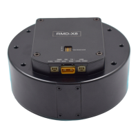
Details the key features of the RMD-X8 motion actuator, including integration and performance.

1.2.1 Control Mode

Describes the available control modes: Torque, Speed, and Position.

1.2.2 Communication Control Mode

Outlines the RS485 and CAN communication modes for controlling the actuator.

2 Installation and Precautions

1.2.3 Encoder Feedback

Details the 14-bit and 18-bit magnetic encoder feedback options.

1.2.4 Technical Highlights

Lists technical advantages such as servo control, high positioning accuracy, and efficiency.

2.1 Installation Dimensions

Provides detailed installation dimensions and diagrams for mounting the actuator.

2.2 Environmental Conditions

Specifies operating and storage conditions: temperature, humidity, altitude, and vibration limits.

3 Electrical Parameters

3.1 Detailed Parameters

Lists comprehensive electrical specifications: voltage, current, power, torque, resistance, and inertia.

3.2 Working Range

Illustrates the operational torque-speed working range graph for the actuator.

3.3 Hardware Connection

Details the physical connections for various interfaces and the power supply.

3.3.1 Interface Specification

Describes connector types and voltage levels for UART, CAN, and Power interfaces.

4 RMD-L config Installation And Parameter Setting

3.3.2 Interface Debugging

Explains the pinout and connection for the debugging interface.

3.3.3 Can interface 1

Details the connection for CAN interface 1, including CANL and CANH signals.

3.3.4 Can interface 2

Details the connection for CAN interface 2, noting its parallel function with CAN1.

3.3.5 Power Interface

Specifies the power interface connection and important notes on voltage and polarity.

5 Communication Protocol

3.4 Multilevel connection line

Illustrates the cascading connection method for multiple actuator nodes.

3.5 Dial code switch Settings

Explains how to configure settings using the dial code switches for address and termination.

3.5.1 Can bus device address Settings (Dial code switch 1 st-3 rd)

Details setting device addresses using the first three dial code switches.

3.5.2 Bus terminal resistance setting (Dial code switch 4 th)

Explains the use of the 4th dial code switch for enabling bus terminal resistance.