15
EASYCUT 40
EN
MAINTENANCE / RECOMMENDATIONS
Ensure the machine is unplugged from the mains, and wait for two minutes before carrying out maintenance work. DANGER High
Voltage and Currents inside the machine.
Maintenance should only be carried out by a qualied person. Annual maintenance is recommended.
1 - Air lter maintenance:
• It is necessary to periodically empty the air lter. To do so, press and hold the orange button below the lter.
• Disassembly:
- Unplug the air supply.
- Grab the tank, press the latch and rotate the bowl 45 degrees to the left.
- Pull the cube downwards and then put it down .
- The ltering part is white, clean or replace it if necessary (ref. 039735).
2 - Periodical maintenance:
• Periodically remove the cover and dust with an air gun. You are advised to have the electrical connections checked by a qualied person, with an
insulated tool.
• Regularly check the condition of the power supply cable. If the power cable is damaged, it must be replaced by the manufacturer, an after sales
service or a qualied person to prevent danger.
• Do not obstruct the machine’s air intake, to allow air circulation.
• Check that the torch does not have any cracks or exposed wires.
• Check that the consumables are installed properly and not worn.
• Do not use this equipment to thaw pipes, to charge batteries, or to start any engine.
INSTALLATION – PRODUCT OPERATION
Only qualied personnel authorized by the manufacturer should perform the installation of the cutting equipment. During set up, the operator must
ensure that the machine is unplugged. Connecting generators in a series or a parallel circuit is forbidden. It is recommended to use the welding cables
supplied with the unit in order to obtain the optimum product settings.
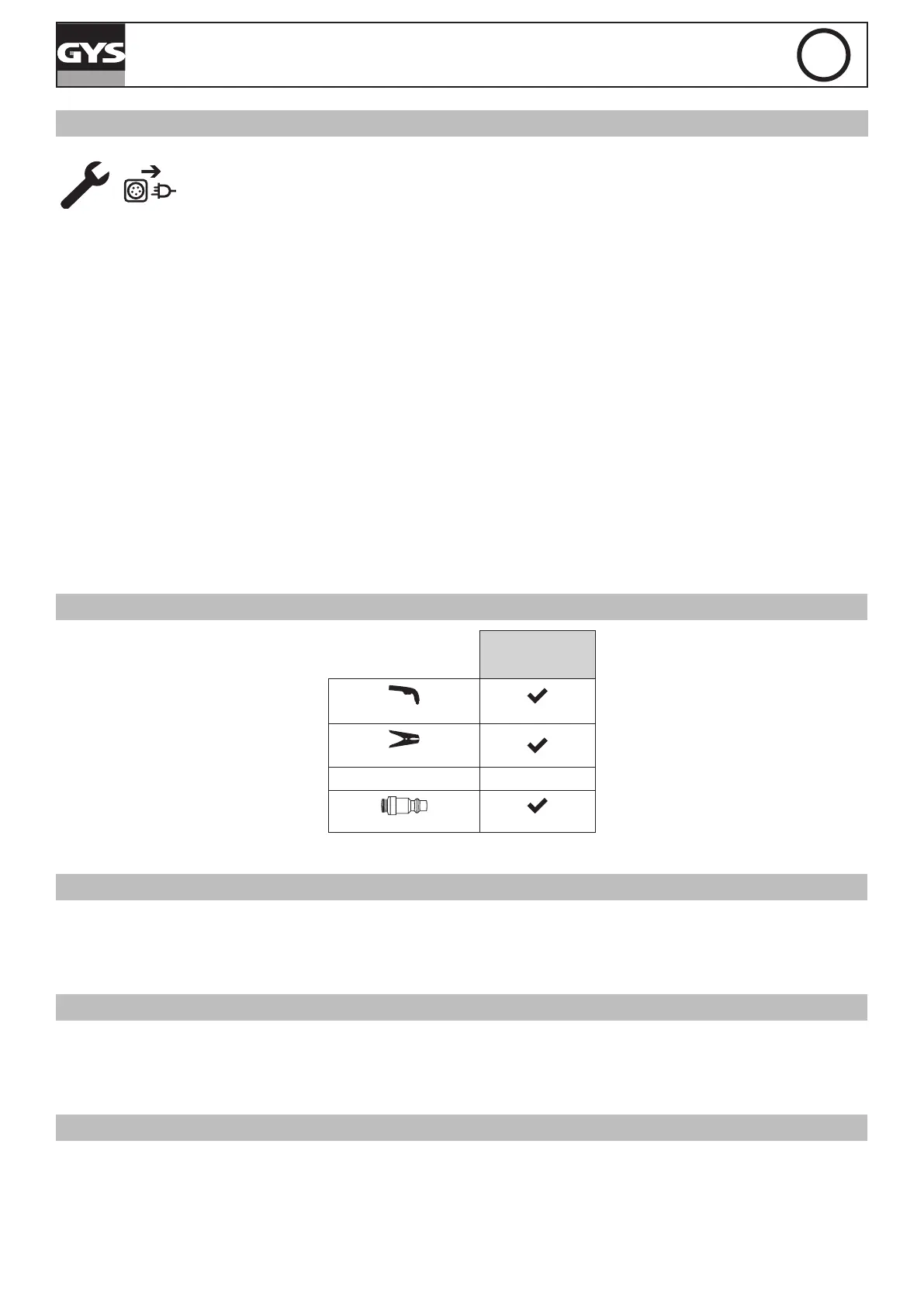
MACHINE SUPPLIED WITH
EASYCUT 40
Ref. 029743
4 m
TPT 40
2 m - 10 mm²
Starting kit
-
Pneumatic ttings
8 mm
The accessories supplies with the machine are to be used only with the same models.
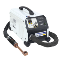
HARDWARE DESCRIPTION (FIG-1)
1- Keyboard + buttons 5- Air lter
2- Torch connector 6- On/off switch
3- Earth clamp connector 7- Power supply cable
4- Compressed air connector 8- Air regulator
(air pressure adjustment)
CONTROL BOARD (IHM) (FIG-2)
1- Power indicator (green) 5- Selection button (air pressure or cutting mode)
2- Thermal protection and over current protection indicator (yellow) 6- Air pressure selection indicator
3- Torch and air pressure fault light 7- Starting the cutting mode indicator
4- Cutting current adjustment 8- Indication to measured pressure value (LED).
POWER SUPPLY – STARTING UP
This machine is tted with a 16A socket type CEE7/7 which must be connected to a single-phase 230V (50 - 60 Hz) power supply tted with three
wires and one earthed neutral. The absorbed effective current (I1eff) is indicated on the machine, for optimal use. Check that the power supply and
its protection (fuse and/or circuit breaker) are compatible with the current required to run the machine (l1max). Use preferably a 32A plug with a 32A
circuit-breaker for intensive use. Position the device so that the socket is always accessible.
They are power supplied by a 230V +/- 15% (50 - 60 Hz) EARTHED installation and are protected to work with generators. This hardware must only
be used with a one phase electricity supply protected by a earthing wire.
The absorbed effective current (I1eff) is displayed on the machine, for optimal use. Check that the power supply and its protection (fuse and/or circuit
breaker) are compatible with the current needed by the machine.