1-8
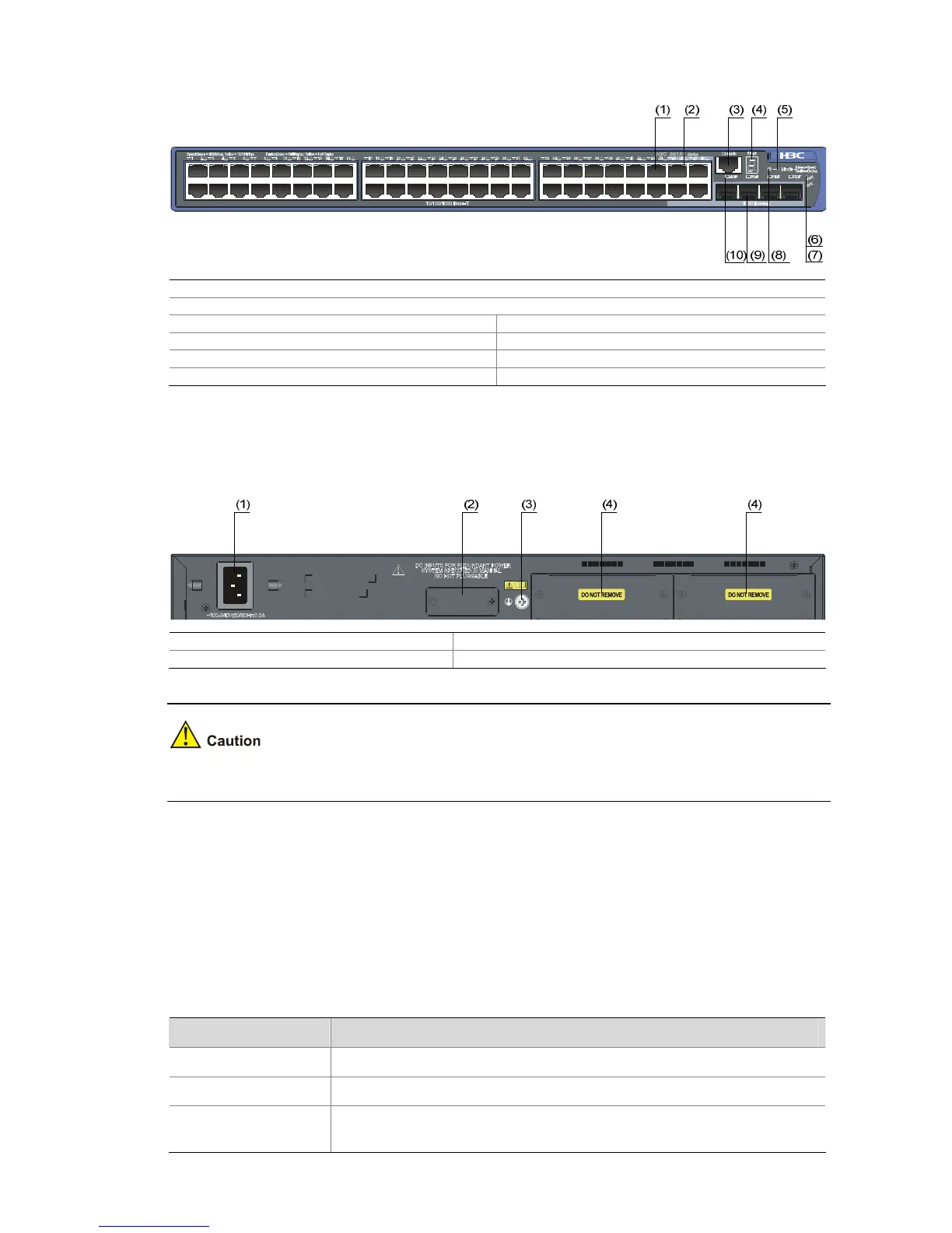
Figure 1-11 Front panel of the S5120-48P-EI Ethernet switch
(1) 10/100/1000 Base-T auto-sensing Ethernet port
(2) 10/100/1000 Base-T auto-sensing Ethernet port status LED
(3) Console port (4) Seven-segment LED
(5) Port mode LED (Mode) (6) System status LED (PWR)
(7) RPS status LED (RPS) (8) Port status LED mode switching button
(9) 1000 Base-X SFP port (10) 1000Base-X SFP port status LED
Rear Panel
Figure 1-12 Rear panel of the S5120-48P-EI Ethernet switch
(1) AC power input (2) RPS power input (shipped with a protective cover)
(3) Grounding screw (4) “DO NOT REMOVE” label
The S5120-48P-EI does not support any interface modules.
Ports
Console Port
Each S5120-EI series provides one console port on the front panel. Table 1-2 describes the console
port specifications.
Table 1-2 Console port specifications
Item Specification
Connector type
RJ-45
Compliant standard
EIA/TIA-232
Transmission baud
rate
9600 bps to 115200 bps (defaulting to 9600 bps)

 Loading...


