3-12
When a Grounding Strip is Available
When a grounding strip is available at the installation site, attach one end of the yellow-green grounding
cable (PGND cable) of the switch to the grounding screw on the grounding strip (the grounding screw
and the grounding hole are on the rear panel of the switch and are marked with a grounding sign). To do
this, follow these steps:
Step1 Remove the grounding screw from the rear panel of the switch chassis.
Step2 Put the supplied OT terminal of the PGND cable on the grounding screw.
Step3 Fasten the grounding screw, which is attached with the OT terminal of the PGND cable, into the
grounding screw hole with a screwdriver.
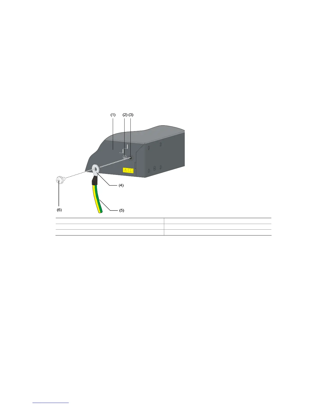
Figure 3-15 Connect the PGND cable to the grounding hole of switch
(1) Rear panel of the switch (2) Grounding sign
(3) Grounding hole (4) OT terminal
(5) PGND cable (6) Grounding screw
To attach the other end of the PGND cable to the grounding strip in the equipment room, follow these
steps:
Step1 Cut the PGND cable to a proper length according to the distance between the switch and the grounding
strip.
Step2 Peel 5 mm (0.20 in.) of insulation sheath using a wire stripper, and then insert the naked metal part
through the black insulation covering into the end of the OT terminal. (Two OT terminals are provided
with the PGND cable when shipped with the switch; select a proper OT terminal according to the size of
the grounding post.)
Step3 Secure the metal part of the cable to the OT terminal with a crimper, and then cover it with the insulation
covering. Then heat the insulation covering with a blowing machine to let it completely cover the metal
part.
Step4 Connect the OT terminal to the grounding pole of the grounding strip, and then fasten it with a hex nut.

 Loading...


