24
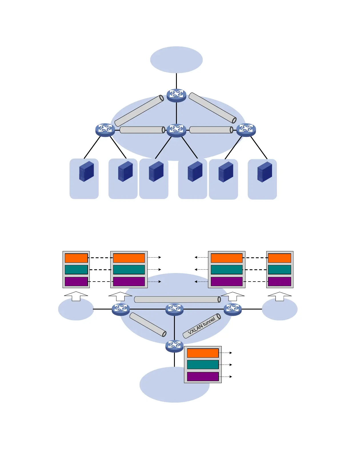
Figure 11 Distributed VXLAN IP gateway placement design
Figure 12 shows an example of distributed VXLAN IP gateway deployment. This section uses this
figure to describe the forwarding processes for intra-VXLAN traffic, inter-VXLAN traffic, and traffic
from a VXLAN to an external network. In these processes, VTEPs use dynamically learned ARP
entries.
Figure 12 Example of distributed VXLAN IP gateway deployment
V
X
L
A
N
t
u
n
n
e
l
V
X
L
A
N
t
u
n
n
e
l
VTEP/Distributed
VXLAN IP
gateway
VTEP
Terminal
Site 1
L3 network
VXLAN tunnel VXLAN tunnel
Terminal
Site 2
Terminal
Site 3
Terminal
Site 4
Terminal
Site 5
Terminal
Site 6
VTEP/Distributed
VXLAN IP
gateway
VTEP/Distributed
VXLAN IP
gateway
VTEP/Border
gateway
VXLAN tunnel
GW 1 GW 2
Site 1
Site 2
Terminal 1
Terminal 2
Terminal 3
VSI/VXLAN 10
VSI/VXLAN 20
VSI/VXLAN 30
Terminal 4
Terminal 5
Terminal 6
VSI/VXLAN 10
VSI/VXLAN 20
VSI/VXLAN 30
P
10.1.1.11
20.1.1.11
30.1.1.11
10.1.1.12
20.1.1.12
30.1.1.12
V
X
L
A
N
tu
n
n
e
l
Border gateway
VSI/VXLAN 10
VSI/VXLAN 20
VSI/VXLAN 30
VSI-interface10
10.1.1.2/24
VSI-interface20
20.1.1.2/24
VSI-interface30
30.1.1.2/24
L3 network
VSI-interface10
10.1.1.1/24
VSI-interface20
20.1.1.1/24
VSI-interface30
30.1.1.1/24

 Loading...


