35
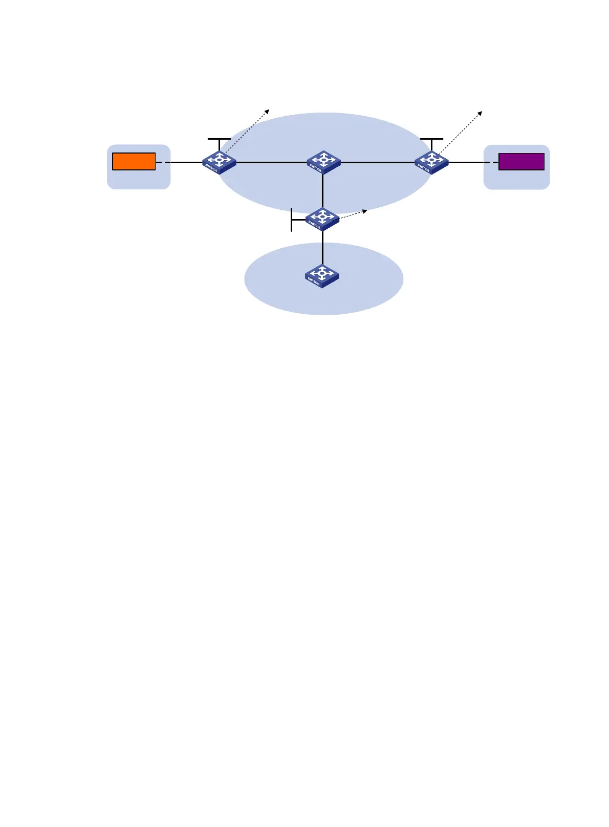
Figure 14 Network diagram
Configuration procedure
1. Set the system operation mode to VXLAN on Switch A, Switch B, and Switch C. This step uses
Switch A as an example.
<SwitchA> system-view
[SwitchA] switch-mode 1
Reboot device to make the configuration take effect.
[SwitchA] quit
<SwitchA> reboot
Start to check configuration with next startup configuration file, please wait..
.......DONE!
Current configuration may be lost after the reboot, save current configuration?
[Y/N]:y
This command will reboot the device. Continue? [Y/N]:y
2. On Terminal 1 and Terminal 3, specify 10.1.1.1 and 20.1.1.1 as the gateway address,
respectively. (Details not shown.)
3. Configure IP addresses and unicast routing settings:
# Assign IP addresses to interfaces, as shown in Figure 14. (Detai
ls not shown.)
# Configure OSPF on all transport network switches (Switches A through D). (Details not
shown.)
# Configure OSPF to advertise routes to networks 10.1.1.0/24, 20.1.1.0/24, and 25.1.1.0/24 on
Switch B and Switch E. (Details not shown.)
4. Configure Switch A:
# Enable L2VPN.
<SwitchA> system-view
[SwitchA] l2vpn enable
# Create VSI vpna and VXLAN 10.
[SwitchA] vsi vpna
[SwitchA-vsi-vpna] vxlan 10
[SwitchA-vsi-vpna-vxlan-10] quit
Switch A Switch C
Transport
network
Switch D
GE1/0/1 GE1/0/1
Switch B
Site 1
Terminal 1
Site 3
Terminal 3
Loop0
1.1.1.1/32
Loop0
3.3.3.3/32
Loop0
2.2.2.2/32
VLAN 2 VLAN 4
Vlan-int11
11.1.1.1/24
Vlan-int13
13.1.1.4/24
Vlan-int12
12.1.1.2/24
Vlan-int11
11.1.1.4/24
Vlan-int13
13.1.1.3/24
Vlan-int12
12.1.1.4/24
Vlan-int20
25.1.1.5/24
Vlan-int20
25.1.1.2/24
Switch E
10.1.1.11 20.1.1.12
VSI-int1
10.1.1.1/24
VSI-int2
20.1.1.1/24
VSI-int1
10.1.1.1/24
VSI-int2
20.1.1.1/24
VSI-int1
10.1.1.2/24
VSI-int2
20.1.1.2/24

 Loading...


