36
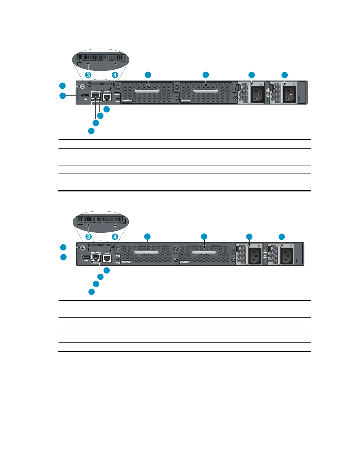
Figure 40 Rear panel (LS-5820V2-52QF)
(1) USB port (2) Grounding screw (auxiliary grounding point 2)
(3) Barcode (4) Product code
(5) Fan tray slot 1 (6) Fan tray slot 2
(7) Power module slot 1 (8) Power module slot 2
(9) Console port (10) LINK LED for the management Ethernet port
(11) Management Ethernet port (12) ACT LED for the management Ethernet port
Figure 41 Real panel (LS-5820V2-52QF-H3)
(1) USB port (2) Grounding screw (auxiliary grounding point 2)
(3) Barcode (4) Product code
(5) Fan tray slot 1 (6) Fan tray slot 2
(7) Power module slot 1 (8) Power module slot 2
(9) Console port (10) LINK LED for the management Ethernet port
(11) Management Ethernet port (12) ACT LED for the management Ethernet port
1
2
3
4
5 6
7
8
9
10
11
12
1
2
3
4
5 6
7
8
9
10
11
12

 Loading...


