4-36
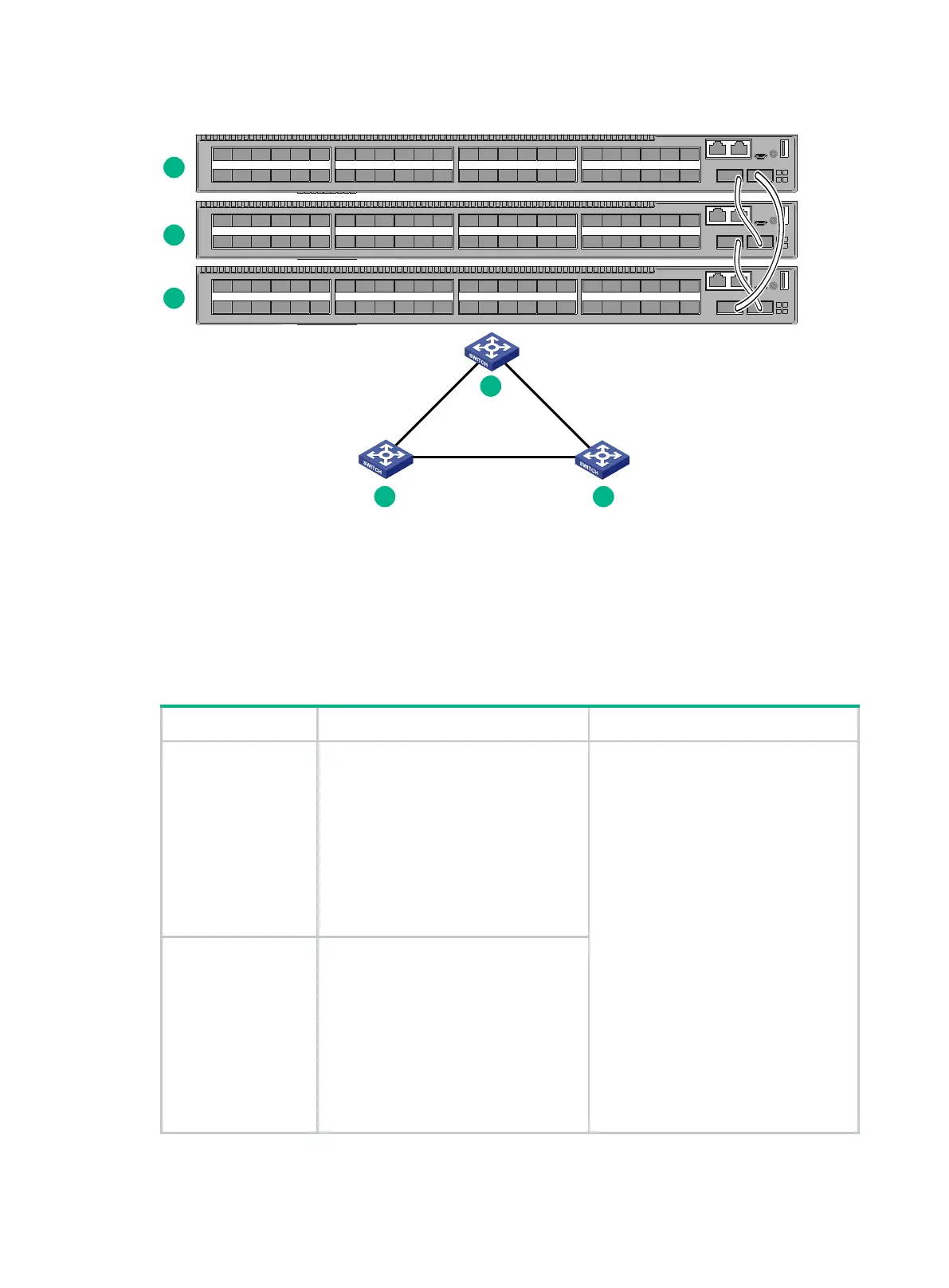
Figure4-3 IRF fabric in ring topology
Identifying physical IRF ports on the member switches
Identify the physical IRF ports on the member switches according to your topology and connection
scheme.
Table4-1 shows the physical ports that can be used for IRF connection and the port use restrictions.
Table4-1 Candidate physical IRF ports and their use restrictions
Chassis Candidate physical IRF ports Use restrictions
S6520X-30QC-EI
S6520X-30QC-HI
• 24 × SFP+ ports on the front panel
• 2 × QSFP+ ports on the front panel
• The following ports provided on the
expansion cards:
5G/2.5G/1000BASE-T
autosensing Ethernet ports
10G/5G/2.5G/1000BASE-T
autosensing Ethernet ports
SFP+ ports
QSFP+ ports
• Physical ports on interface
modules and the front panel can be
bound to the same IRF port.
• All physical ports to be bound to an
IRF port must have the same data
rate.
• A QSFP+ port that is split into four
virtual SFP+ ports cannot be used
as a physical IRF port.
• A QSFP28 port that is split into four
virtual SFP28 ports cannot be used
as a physical IRF port.
S6520X-54QC-EI
S6520X-54QC-HI
• 48 × SFP+ ports on the front panel
• 2 × QSFP+ ports on the front panel
• The following ports provided on the
expansion cards:
5G/2.5G/1000BASE-T
autosensing Ethernet ports
10G/5G/2.5G/1000BASE-T
autosensing Ethernet ports
SFP+ ports
QSFP+ ports
1
2
3
IRF-port1
IRF-port2
IRF-port1
IRF-port1
IRF-port2
IRF-
port
2
1
2
3

 Loading...


