W A R N I N G
Fire hazard. Relay loads must be resistive. Always limit current to the relays with an external fuse or
breaker. Obey the relay ratings in the Specifications section.
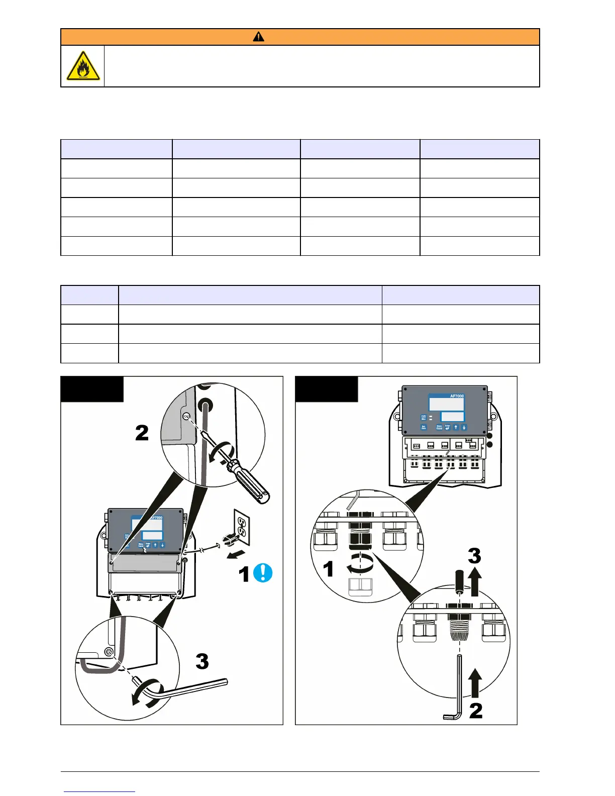
Refer to the illustrated steps in this section to connect the instrument to external devices or to a
communications network. For connection to the wire terminals, refer to Table 1 and Table 2.
Table 1 Optional device wiring
Option Pin name (description) Pin name (description) Pin name (description)
4–20 mA Sh (shield with ground) + (positive) – (neutral)
Modbus (RS485) Sh (shield without ground) Tx (transmit) Rx (receive)
Alarm relays NC (normally closed) Com (common) NO (normally open)
External PID controller Sh (shield) + (positive) – (negative)
Digital input 1 (input 1) 2 (input 2) Com (common)
Table 2 Autoflush card wiring
Pin Description Wire color
P Phase Black—1
N Neutral Black—2
E Protective earth ground Green/yellow
1 2
12 English
 Loading...