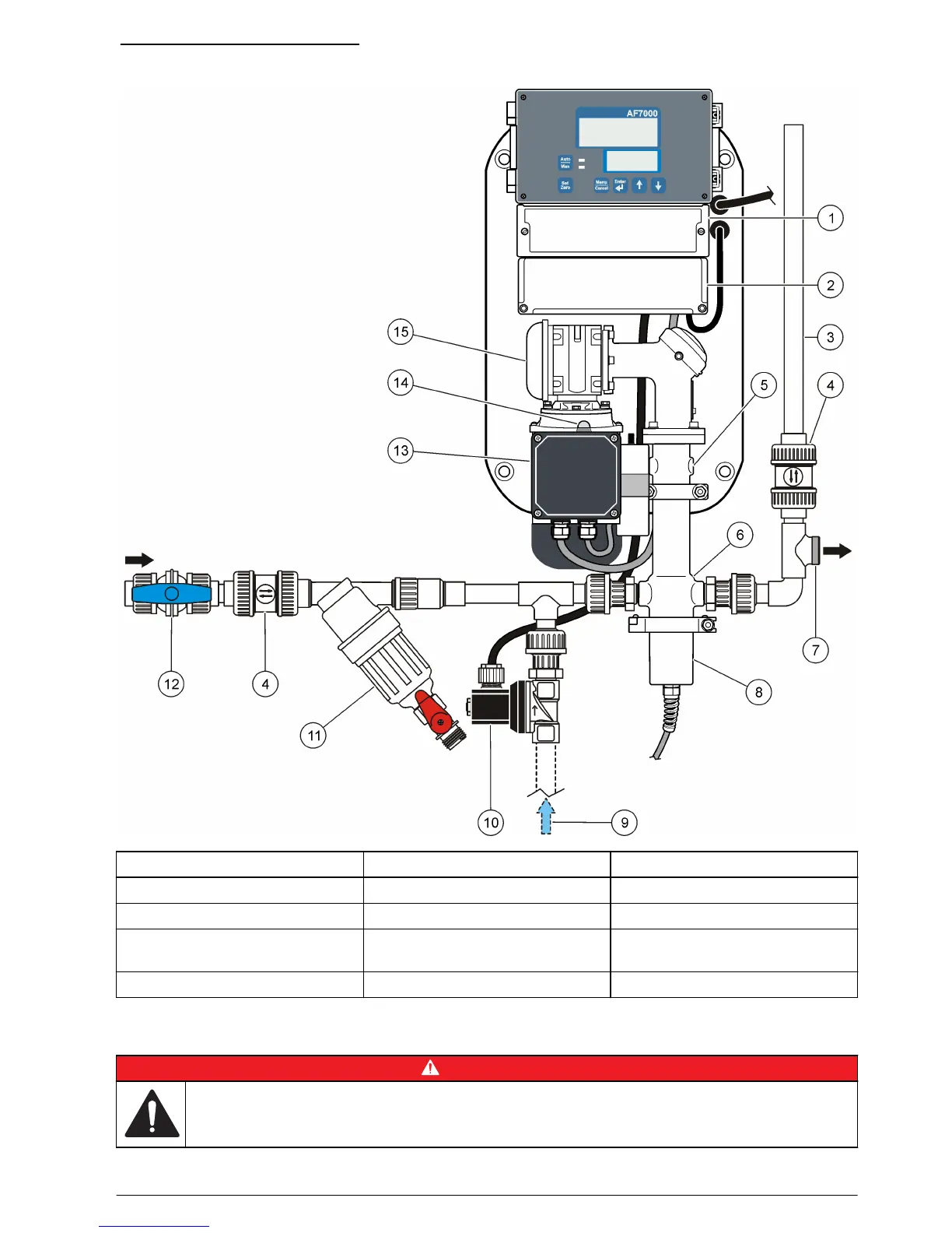
Figure 1 Instrument overview
1 Wiring access cover 6 Sample chamber 11 Grit filter
2 Cable access cover 7 Sample outlet 12 Manual isolation valve for inlet
3 Head height indicator pipe 8 Sensor 13 Motor
4 Directional valve 9 Clean water in (for optional
flush)
14 Reset switch for motor
5 Overflow port (2x) 10 Optional flush valve 15 Gearbox
Installation
D A N G E R
Multiple hazards. Only qualified personnel must conduct the tasks described in this section of the
document.
English 7