Do you have a question about the Hafler DH-101 and is the answer not in the manual?
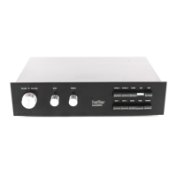
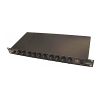
Introduces the Hafler DH-101 preamplifier, highlighting its low distortion, high quality components, and operational flexibility.
Illustrates how to connect the DH-101 preamplifier to various audio components like turntables, tuners, and amplifiers.
Explains the preamplifier's core functions, sophisticated circuitry, and commitment to sonic fidelity and performance.
Details connections for turntables, including impedance and ground wire considerations for optimal sound.
Describes connections for tuners and other auxiliary equipment with moderate level signals.
Explains how to connect tape recorders for playback, including considerations for decks without pre-amplification.
Guides on adjusting volume, balance, and tone controls for optimal sound shaping and listening experience.
Details switches for selecting audio sources like Phono, Tuner, and Aux.
Explains switches for tape operations (Play, Dub), Mono mode, Tone engagement, and Power control.
Details how to configure the DH-101 for 100, 120, 200, 220, and 240 volt AC lines using transformer taps.
Instructs on replacing fuses, specifying different ampere ratings for different voltage ranges.
Explains how to use Tape 1 and Tape 2 buttons for listening to tape playback and monitoring recordings.
Describes the functionality of the MONO button for switching between stereo and mono audio modes.
Provides three fundamental rules for successful electronic kit construction: follow instructions, make good connections, and check work.
Lists the essential tools needed for building the DH-101 kit, including soldering iron, solder, and pliers.
Details the four essential steps for creating reliable solder connections, emphasizing heat, solder application, and cooling.
Emphasizes using rosin core solder, proper iron temperature, and tinning wires for secure connections.
Guides on preparing wires, stripping insulation, and handling delicate components to prevent damage.
Explains how to use the pictorial diagram for identifying components and tracing wire connections during assembly.
Covers preparing the chassis, front plate, and separating hardware for organized assembly.
Details attaching rubber feet to the bottom plate and preparing knobs for mounting.
Guides on installing AC outlets, input socket strips, and ground lugs onto the back panel.
Covers mounting the power transformer and power supply board onto the chassis brace.
Details connecting wires to the PC-3 switch board and associated components like capacitors.
Explains weaving and soldering ground wires through input socket lugs and connecting capacitors to ground points.
Guides on installing the AC line cord and strain relief through the back panel, ensuring proper orientation.
Details connecting the AC line cord to outlet lugs and wiring AC outlet lug #1 to lug #2.
Provides instructions for connecting multiple wires to input socket lugs, including wire preparation and tagging.
Offers techniques for wiring narrow switch lugs, emphasizing wire insertion, soldering, and clipping excess leads.
Details connecting wires to the PC-1 power supply board, including transformer leads and jumper connections.
Guides on trimming and connecting transformer leads to specific eyelets on the power supply board.
Shows the connections between PC-3, PC-2, and PC-4 circuit boards, illustrating the audio signal path.
Illustrates the wiring of the power transformer for different voltage inputs, including fuse placement.
Presents the detailed schematic for the 120V AC power supply, including regulators and filters.
Shows the specific schematic configuration for operating the power supply on 220V AC lines.
Displays the schematic for the 240V AC power supply configuration, highlighting any differences.
Lists all resistors and capacitors used in the DH-101, their values, and corresponding part numbers.
Details transistors, diodes, ICs, fuses, controls, and the power transformer with their part numbers.
Provides further instructions for connecting wires to switch lugs, emphasizing careful routing and soldering.
Guides on using plastic wire ties to bundle wires neatly and secure them to the chassis and brace for optimal appearance and function.
Explains how to mount the PC-4 circuit board to the front panel using the control shafts and nuts.
Details the specific connections of various wires to the numbered eyelets on the PC-4 board for final assembly.
Guides on installing the LED pilot lamp, including preparing support wires and soldering connections for proper illumination.
Provides the last set of instructions for connecting wires to switch lugs, ensuring all connections are secure and properly routed.
Outlines critical checks for soldered connections, wire routing, and potential short circuits before final assembly.
Explains how to use plastic wire ties to bundle wires for a clean appearance and secure routing within the chassis.
Details inserting jumpers into the "Ext. Patch" sockets to complete the signal path when no external units are used.
Guides on installing the fuse and ensuring wires do not obstruct holes for cover and bottom plate screws.
Covers attaching the bottom plate and front plate, including positioning the LED lamp and tightening control nuts.
Details installing the cover, ensuring no wires are pinched, and adjusting the balance and tone control knobs for proper operation.
Provides initial steps for fault diagnosis, checking connections, and isolating problems to specific sections or cables.
Offers guidance on identifying and resolving hum, noise, and problems affecting only one audio channel.
Suggests diagnostic methods for power supply and amplifier sections, including checking voltages and transistor substitution.
Illustrates the DH-101's sections and describes the regulated ±18 volt DC power supply operation.
Explains the design of the phono, tone control, and high-level amplifier sections, highlighting their performance characteristics.
Discusses the conventional switching circuits and the buffered outputs to tape recorders and external units.
Outlines the policy for returning units for factory repair, including shipping instructions and required documentation.
Lists conditions under which the preamplifier's warranty becomes void, such as physical abuse or unauthorized modifications.
Details the warranty terms for both kit-built and factory-assembled units, covering parts, labor, and return procedures.
Lists delicate components, hardware, and the pre-assembled circuit boards included in the kit.
Details capacitors, resistors, transistors, diodes, and other electronic components with their part numbers.
Includes items like audio cable pairs, input socket strips, labels, line cords, transformers, and wire ties.
Details the performance metrics for the phono preamplifier, including output, distortion, overload, and frequency response.
Lists specifications for the tone control and high-level amplifier sections, covering output, distortion, and frequency response.
Covers overall specs like semiconductor count, inputs/outputs, controls, power, dimensions, and weight.
| Type | Preamplifier |
|---|---|
| Output Impedance | 600 Ohms |
| Signal-to-Noise Ratio | 90 dB |
| Power Supply | AC 120V |
| Gain | 20 dB |
| Dimensions | 17" x 10" x 3.5" |