4500 Series Electric Lever Trim
Electrical Supplemental Instructions
Grade 1
I-ED00370
REV 3
Page 2 of 3
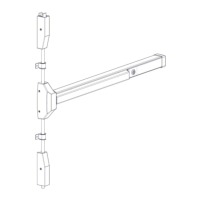
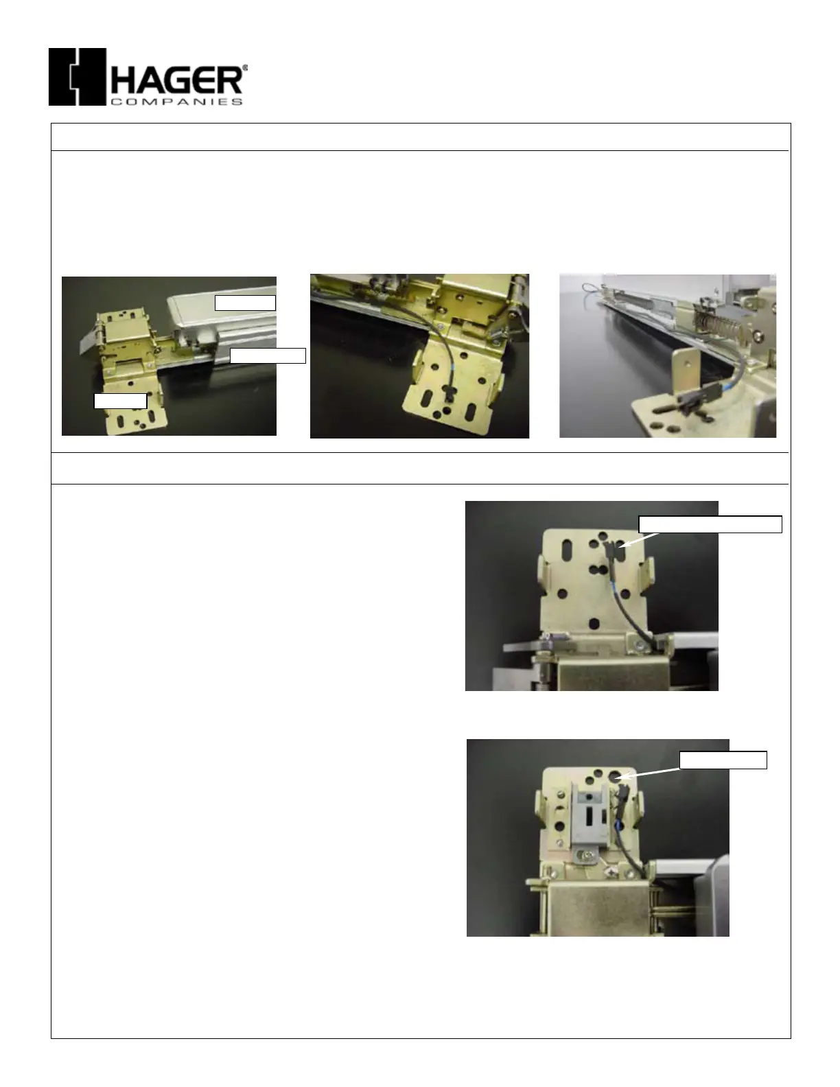
2. PREPARE EXIT DEVICE
A. Remove four (4) screws from chassis cover and remove.
B. Separate chassis/push bar from device body by removing two (2) screws located on chassis.
C. After chassis/push bar has been removed from device body, insert cable assembly along the side of push bar. Make sure that
connector end is located on the chassis side.
D. After cable assembly has been routed on the side of the push bar, re-install the device body and secure with the two (2) screws.
CHASSIS
DEVICE BODY
PUSH BAR
3. ROUTE CABLE
RIM Device
A. Feed the connector on the trim control through the .500
diameter prep hole of door and through the slotted hole in
RIM device chassis.
B. Connect the cable assembly to the connector on the trim
and finish mounting the devices per the manufacturers
instructions.
Conceal and Surface Vertical Rod Devices
A. Feed the connector on the trim control through the .500
diameter prep hole of door and through the hole in surface
vertical rod chassis.
B. Connect the cable assembly to the connector on the trim
and finish mounting the devices per the manufacturers
instructions.
CHASSIS HOLE
27390028
SLOTTED CHASIS HOLE
 Loading...