4501 On-Board Delayed Egress Installation
Instructions
I-EA00156
Rev 1, Rev Date: 9/28/19
Always visit www.hagerco.com for the latest Installation Instructions
HAGER COMPANIES 139 Victor Street, St. Louis, MO 63104 • (800) 325-9995
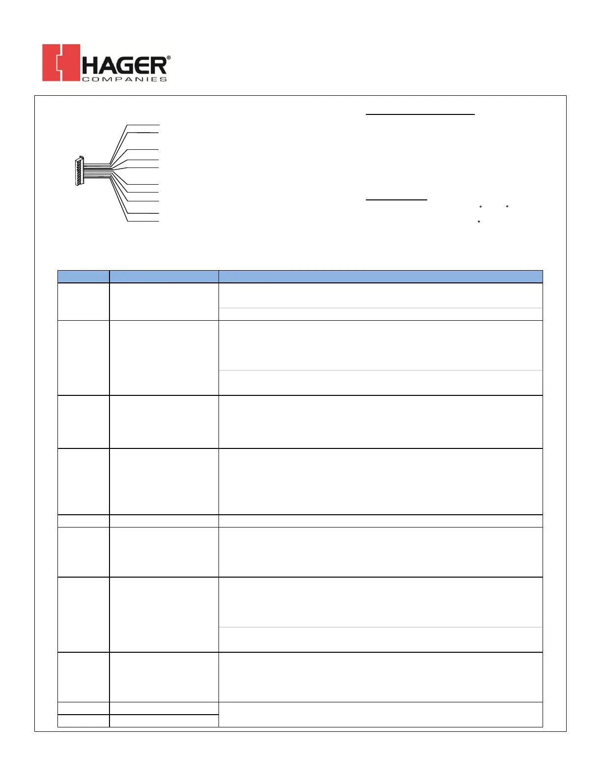
Device Wiring Pigtail
A DOOR CONTACT IS REQUIRED FOR ANTI-TAILGATE AND DOOR PROP FUNCTIONS.
2
THESE WIRES SHALL BE CONNECTED TO AN ACCESSORY IN THE PROTECTED AREA.
UNUSED WIRES SHOULD BE CAPPED OFF.
1
Max Operating Temperature: 0 C to 70 C
Tested to 85% RH @30 C
Enviromental:
Input Voltage : 24VDC +/- 10%
Slave Output : 24VDC @250ma
Monitor Relays: 1 Amp contacts @12/24vdc
Input Current : 540ma Max
Electrical Specifications:
GRY = DPS
1,2
ORG = Slave Out
1
VIO = Remote Trigger
1
BRN = Red Relay
1
GRN = Green Relay
1
YEL = Relay Common
1
BLU = Reset / REX
1
WHT = Bypass
1
RED = Power In (+)
BLK = Power In (-)
(24VDC)
(For pairs of doors)
(24vdc @ 250ma)
Wire Color Wire Designation Description
Used for a pair of doors (master & slave). This is a voltage output (24VDC @250mA).
Connect this wire to +24VDC (Red wire) of the slave bar.
See "Typical Wiring for Double Door Installation".
Used for a pair of doors (master & slave). This is a dry input. Connect this wire to
one leg of the Slave Trigger output. The other leg of the Slave Trigger output is
connected to ground (-VDC). Closing the switch shorts this wire to ground and
initiates the alarm sequence.
See "Typical Wiring for Double Door Installation". The two white wires on the
slave bar are the Normally Open trigger switch.
Brown Red Relay
This is the Alarm Relay Output (Dry, 1A@12/24VDC). It is normally INACTIVE when
the door is secure. It changes state when the bar is pressed beyond the nuisance
delay and placed into an Alarm state. It may be configured as Normally Open OR
Normally Closed using Jumper J7. The YELLOW wire is the relay common.
Green Green Relay
This is the Door Secure Relay Output (Dry, 1A@12/24VDC). It is normally ACTIVE
when the door is secure. It changes state when the bar unlocks after (a) the
delayed egress countdown expires, (b) an authorized Request-to-Exit(REX) signal,
or (c) the bar is Bypassed. It may be configured as Normally Open OR Normally
Closed using Jumper J6. The YELLOW wire is the relay common.
Yellow Relay Common
This is the shared relay common for both the Red & Green Relay.
Grey Door Position Switch (DPS)
This is a dry input. Connect this wire to one leg of a Door Contact switch. The other
leg of the Door Contact switch is connected to ground (-VDC). The Door Contact
polarity must be OPEN when the door is closed. A door contact is required for anti-
tailgate and door prop alarm functions.
This is a momentary, dry input. Connect this wire to one leg of a Normally Open
switch. The other leg of the Normally Open switch is connected to ground (-VDC).
When the bar is in a secure state, shorting this input will result in an authorized
unlock (REX). The REX period is configured by the dip switch settings.
When the bar is in an alarm, authorized unlock state, or in a bypassed state,
shorting this input will reset (secure) the bar.
White Bypass
This is a momentary, dry input. Connect this wire to one leg of a Normally Open
switch. The other leg of the Normally Open switch is connected to ground (-VDC).
When the bar is in a secure state, shorting this input will unlock the device
indefinitely, until the bar is Reset.
Red Power IN (+) 24VDC
Black Power IN (-) 24VDC
Input Voltage: 24VDC +/- 10%; Input Current: 540mA (max). The Red & Black wires
are the minimum required connections.
 Loading...