4501 On-Board Delayed Egress Installation
Instructions
I-EA00156
Rev 1, Rev Date: 9/28/19
Always visit www.hagerco.com for the latest Installation Instructions
HAGER COMPANIES 139 Victor Street, St. Louis, MO 63104 • (800) 325-9995
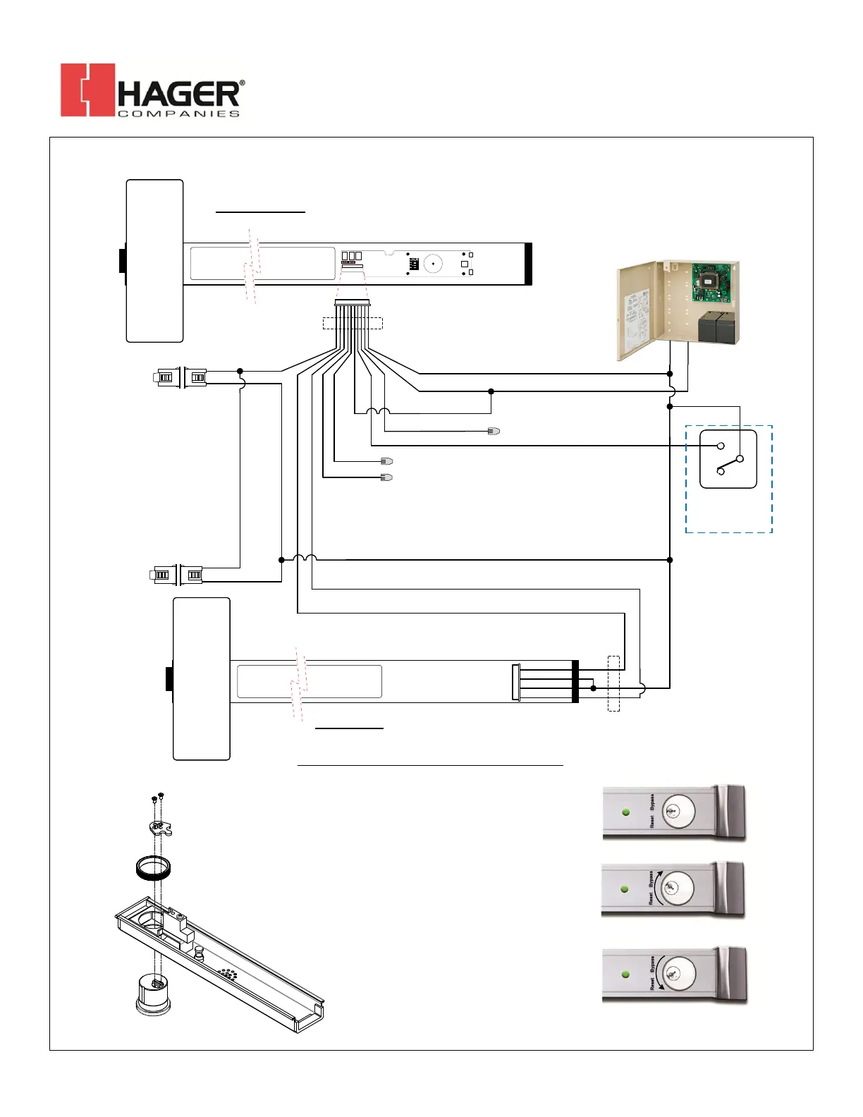
BLU (Reset/REX)
WHT (Bypass)
RED (+)
BLK (-)
Power
Transfer
24VDC
TYPICAL WIRING FOR SINGLE OR DOUBLE DOOR INSTALLATION
YEL (Rly – COM)
2909
POWER
SUPPLY
GRN
BRN
MASTER
Power
Transfer
SLAVE
PIGTAIL
WHT
WHT
BLK
RED
VIO (Remote Trig)
ORG (+24VDC Out)
2-679-0626**
Door
Contact
(Master)
2-679-0626**
Door
Contact
(Slave)
GRN
WHT
GRY
(DPS)
GRN
WHT
**Door Contact connection is optional,
but required for anti-tailgate and door
prop alarms. 2-679-0626 is included
with Master Unit
NOTE: Red & Blk pigtail wires are
the minimun required connections.
KEY CYLINDER INSTALLATION & OPERATION
Key cylinder is in the normal, center
position. LED is solid green when the
device is secure.
To bypass the device for an extended
period of time, momentarily turn the
key cylinder towards “Bypass” and
return to the center position. LED will
flash slowly.
When the device is in a secure state,
momentarily turning the key cylinder
towards “Reset” will result in a timed
authorized unlock (REX).
When the device is in an alarm, authorized
unlock, or bypassed state, momentarily
turning the key cylinder towards “Reset”
will re-secure the device.
Hager 4501 OBDE
4501/4601 DE
ACCESS
CONTROL
SYSTEM
C
N/C
N/O
24VDC
+(-)
INSTALL CYLINDER LOCK
(NOT SUPPLIED) INTO
DEVICE COVER AS SHOWN
 Loading...