Functions and control
Domestic air conditioner
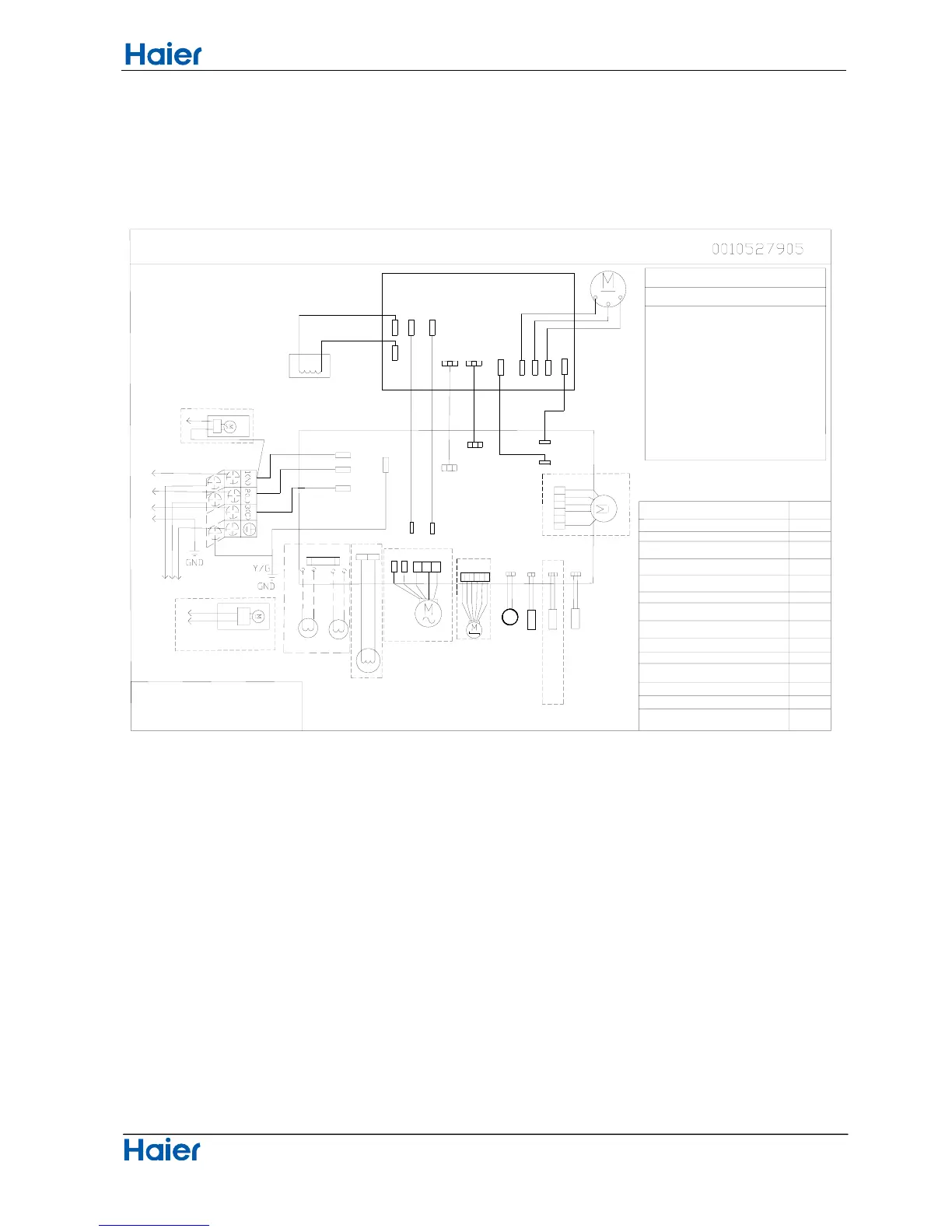
Wiring diagrams
W:WHITE
W
V
U
B
W
R
R
CN13
CN10
CN16
AMBIENT
SUCTION
BL
BL
CN20
CN15
CN14
P
E
CN22
C
N
1
C
N
5
CN6
CN7
CN26
CN24
CN10
BL
CN19
CN18
CN17
CN1
CN2
CN4
OR
CN23
CN11
C
N
4
C
N
3
C
N
2
CN3
CN9CN8
CN9
CN8
AC-LAC-N
AC-L
AC-N
OUTDOOR WIRING DIAGRAM
WARNING
CAUTION
DON'T TOUCH CAPACITOR, EVEN AFTER
PLUG-OFF ( DANGER OF ELECTRIC SHOCK)
The capacitor retains high
voltage even after the plug-off.
For your safety, be sure to wait
at least 5 minutes. after plug
off and use a tester to confirm
the voltage between connector P
and N(on module board) is less
than DC 10V before start
servicing.
PFC REACTOR
MODULE BOARD
MAIN CONTROL BOARD
AC FAN MOTOR
4-WAY VALVE
EXPANSION VALVE
ELECTRIC
Remark:the dotted parts are
optional for different unit.
to double-way air
exchange motor
air exchange motor
to single-way
DEFROST
TEMP.SENSOR
TEMP.SENSOR
TEMP.SENSOR
COMPRESSOR DISCHARGE
TEMP.SENSOR
DC FAN MOTOR
CN21
3.15A/250VAC
F
U
S
E
2
CN11
Electric
Heating Cable
TO INDOOR UNIT
TERMINAL
BLOCK
POWER
CN36
Description
LED1 Flash
1
2
3
4
8
6
5
13
19
18
12
10
Times
24
25
Outdoor EEPROM error
The protection of IPM
Communication fault
Overcurrent protection
Overheat protection for
Over pressure or Overheat
Deviate from the normal
Exhaust temperature sensor failure
Ambient temperature sensor failure
of AC electricity
between the IPM and CBD
protection for the compressor
Power voltage is too high or low
exhaust temperature
Frost-removing temperature
sensor failure
for the compressor
Loop of the station detect error
Overcurrent of the compressor
Overcurrent protection for
single-phase of the compressor
BL(OR W)
(OR B)
BR
BL(OR W)
BR(OR B)
BL:BLUE
BR:BROWN
R:RED
B:BLACK
Y/G:YELLOW/GREEN
OR:ORANGE