Service Manual
Model No.:
- 11 -
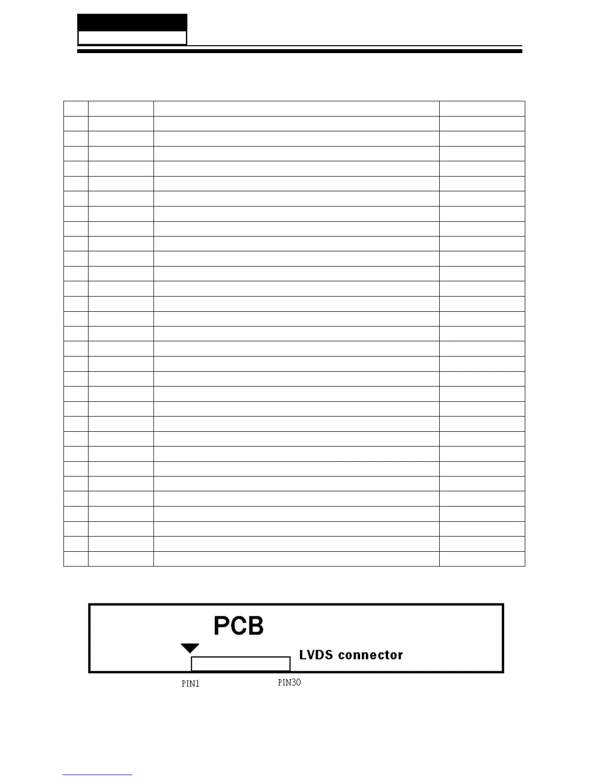
3-4-1.Connector de finition
Pin Name Description Remark
1 VCC +12.0V power supply
2 VCC +12.0V power supply
3 VCC +12.0V power supply
4 VCC +12.0V power supply
5 GND Ground
6 GND Ground
7 GND Ground
8 NC
No connection
(2)
9 SELLVDS Select LVDS Format (3)(4)
10 NC NC (2)
11 GND Ground
12 RX0- Negative LVDS differential data input. Channel 0
13 RX0+ Positive LVDS differential data input. Channel 0
14 GND Ground
15 RX1- Negative LVDS differential data input. Channel 1
16 RX1+ Positive LVDS differential data input. Channel 1
17 GND Ground
18 RX2- Negative LVDS differential data input. Channel 2
19 RX2+ Positive LVDS differential data input. Channel 2
20 GND Ground
21 RXLCK- Negative LVDS differential clock input.
22 RXCLK+ Positive LVDS differential clock input.
23 GND Ground
24 RX3- Negative LVDS differential data input. Channel 3
25 RX3+ Positive LVDS differential data input. Channel 3
26 GND Ground
27 NC No connection (2)
28 NC No connection (2)
29 NC No connection (2)
30 GND Ground
Note (1) Connector type: (P-TWO=187053-30091 or FOXCONN=GS23302-1321S-7H )
ʳʳʳʳʳLVDS connector pin orderʳdefined as follows
 Loading...