10
LN
PQ
CONTROL
BOARD
P
ACL
ACL
ACN
H PS TD TE
(1)
TS TA
ACN
BM1BM2
CN1
CN19
PTC
CN2
CN3 CN4CN5
CN6
CN7
LED4 LED2
CN29CN28
CN21
CN24
CN10
CN9
CN8
EEV
CN30
6.3A 250VAC
FUSE1
CN18
CN17
CN16
CN25
CN15
CN12
ACFAN2
SW1SW3
SW4
DCFAN1
SW2
HEATER
4WV
SV1
NO
1234567
8
NO
12345678
M
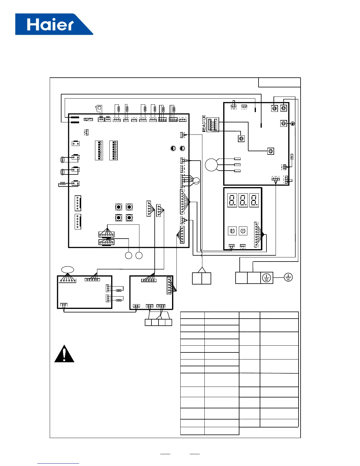
<WARNING>
PC
CN20
CN14
ACFAN1
CN13
DCFAN2
AC-N
AC-L
DK2
DK1
U
V
W
C O MP
R
B
W
INV BOARD
Tfin
CN8
CN1
PE
DISPLAY
BOARD
CN31 CN32
CN30
SW01
LD1 LD2 LD3
SW02
0150518287
M
ACN
ACL
Please power off firstly for about 10
minutes before checking control box,
and make sure the voltage between
P and N below 20V.
Please check the power firstly before test, and make
sure the crankcase heater powering on for 12 hours
at least to protecting compressor.
Forbid connecting the power wire to the "P" and
"Q" otherwise the control board will be damaged.
Please make sure the earth wire connecting the grou-
nding hole on the electric box firmly.
SV1
SV2
4WV
LED1-4
DCFAN2
DCFAN1
DC Fan Motor
DC Fan Motor
HPS
Td
High Pressure
Switch
High/low Pressure
Switch
Compressor
Vent Sensor
Symbol Signification
Power Line
Power Zero Line
Unloading Valve
Spray Valve
Four-way Valve
Lights
Symbol Signification
Defrost
Temperature
Sensor
Ts
Ta
TE(1)
Tc1/Tc2
Tfin
EEV
SW1-4
BM1,2
Compressor
Inhale Sensor
Ambient
Temperature
Sensor
Electronic
Expend Valve
Ipm Temperature
Sensor
Electric
Heating Tape
Digital
Display Tubes
Button
Thumbwheels
Dial Switch
Monitor
M
<NOTES>
CN13
CN12
JP3
R
B
Ps Pd
CN11
CN7
0151800273 0151800303
CN31-1
CN11-1
CN31-2
CN1
CN34
ABG
12V
CN8
CN9
CN11
!
CN31
CN33
Tc1
Tc2
P M V2
CN5
PS/Pd
HEATER
LD1-3
SW01,02
Pipe Sensor
5. Wiring
Diagram
AU04/05/062FPERA