31-5000496 Rev. 1 9
Installation Instructions
Console Installation
NOTE: Be sure to keep all piping and electrical
wrapped as tight as possible to ensure the unit will sit
flush against the wall.
Allow slight slack in the piping to allow for easier
positioning and serviceability.
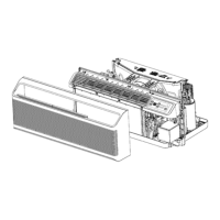
Step 6: Indoor Unit Placement
A. Floor Mount
1. Fasten the unit to the floor through the 2 floor
mounting screw holes located in the front of the base
of the chassis.
2. Fasten the console unit to the wall through the 4 wall
screw holes at the rear of the chassis. Tighten the
screws securely.
Screw Holes for Floor Mount
(Front View)
B. Mounting the Indoor Unit on the Wall
1. Hook the top of the console unit onto the wall
mounting bracket.
2. Fasten the console unit to the wall through the 4 wall
screw holes at the rear of the chassis. Tighten the
screws securely.
Screw Holes for Floor Mount
(Front View)
Wall Screw Holes
Console Installation
Step 7. Wiring Connections
NOTE: The unit should be installed by a licensed
contractor/electrician. If required by applicable national,
state and local codes; a disconnect switch will need to
be installed when the indoor unit is powered from the
outdoor unit.
1. Lift the panel containing the WiFi module and
diagnostic port.
2. Remove the screw on the right side of the cover and
remove the cover.
3. Make wiring connections at each terminal according
to wiring diagram. (Take note of the color of the wire
at each terminal and ensure the wires are connected
to the outdoor unit accordingly.)
4. Secure the cable to the indoor unit using the strain
relief strap.
5. Replace the board cover and lower the panel.
1.
4.
2.
WARNING
When making power supply connections, connect
wires of the same specification and wire size (as
described below)
 Loading...